
Vintage RCA Color TV Page Three
By
The Worthington
Listen to this page on our podcasts. 🎶
Continuing the restoration of RCA CTC-7 Worthington from Page One.
DAY 60, MAY 15, 2017
On July 29, 2015, we placed this set on hiatus.
A brief summary from Vintage RCA Color TV Page One:
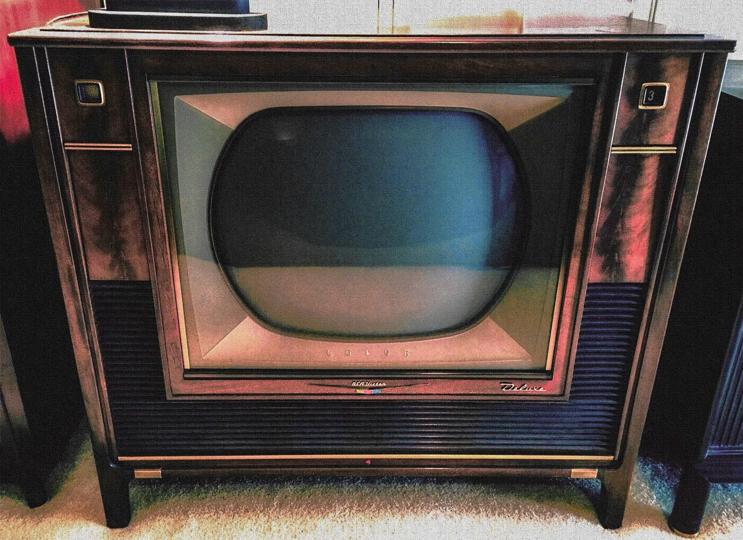
We became the custodian of this set on June 1, 2015 from the Estate of Ed Reitan. The set has an innovative wireless remote control for the time, a 7 function, 14 push button hand held control. This television was the first to introduce wireless remote to a color set and with no visible, outward controls, the cabinet has a sleek contemporary appearance. This high end, top of the line set gave RCA a technological tour de force in 1958.


All the functions of the set are controlled by this remote via, solenoids, a servo motor and a duplicate hard wired control panel which tuck away, out of site when the set is not in use. This set was unused for a long period and upon opening the cabinet and initial inspection, we discovered the gear box was locked up, rendering all controls inoperable. Today we undertake the full, complete restoration of the RCA CTC-7 Worthington.
Today, my friend Mike picked up the chassis’s, control panel, remote and took them to his shop. Mike restored our RCA 21CT55. The CRT and cabinet remains with me. I will also be involved in the restoration.
Brief notes:
The CRT emissions are good with good cutoff. We discovered that the 21CYP22A was rebuilt. In the last photo below, you can see the weld and I can feel the depression in the glass. The 21CYP22 was the first all glass CRT built by RCA. The 21CYP22A was a modification. You can see various views of the main chassis and hard wired control panel. A quick look at the flyback transformer checks out okay.
In the month’s ahead, we will chronicle our restoration as we did with the 21CT55 shown on Pages One and Two.
Tap on any image for enlargement.


DAY 71, MAY 26, 2017
From Mike today:
HI Marshall. I have spent several evenings working on the servo issues. So far I have determined that the gearbox is OK. YAY. I found a failed NON Polarized capacitor which serves the purpose of “starting” the motor which drives the gearbox. I then had motor activity in one direction however it was very sluggish. I had to remove the motor and direction sensing switch assembly and do a thorough cleaning. I then re-assembled the motor with a fresh coat of lubricating oil, polished the contacts on the sensing switch and re-assembled that. I can now control all of the seven functions from the local control buttons. The direction sensing switch was responsible for the single direction issue. The fine tuning will need some mechanical work but the servo section is working. This is all a major accomplishment in the process. The gearbox had me worried. I will mention now, that the gear on the end of the motor armature is NYLON molded to the STEEL motor shaft and it should be considered the most delicate component in the entire system. I really wish that manufacturers would not do those things. There is no reason whatsoever for it except that it makes them more money as long as these products are in circulation and working. After that, they become rare as “hens teeth’. The nylon gear section is notorious for cracking and separating from the steel armature shaft on this type of motor. THIS ONE IS FINE SO FAR.
I have some pictures to add but it is too late for me right now. I will send them hopefully tomorrow night. The next step is to jig the chassis and take a look at the general operation. Then I will go on to the remote receiver issues and the hand unit issues.
Here are the pictures from the last couple of nights work.
1. On the bench before jigging with the sweep circuits disabled.
2. The motor and direction sensing switch disassembled.
3. Screws, springs, bearings, and armature showing the NYLON gear head.
4. Remote receiver on another bench ready for checkout.
5. A better shot of the direction sensing switch before cleaning, polishing and adjusting.
6. The “patched in” blue capacitors which will replace the existing NON Polarized device. A terminal strip will have to be installed here because the new capacitors mount differently than the original.
Regards, Mike
Author:
This is great news Mike. As to the armature, modern imported products get a bad rap for planned obsolescence (untrue in my opinion) and here we are in 1958 taking questionable shortcuts.


DAY 85, JUNE 9, 2017
Author:
After much thought, it was decided to leave the armature as is. The consensus, “you need a watchmaker to replicate …. better to try and find a suitable replacement.”
From Mike:
“Greetings Marshall. I successfully jigged the chassis tonight. The first thing that is GLARING at me is that the tuner is very erratic. That will be the first thing that I have to address on this project. I’m not sure if there are bad connections or poor solder joints in there or “what”? I will also be testing all of the small tubes before I continue.
More later, Mike”
DAY 86, JUNE 10, 2017
From Mike:
Hi Marshall. I have removed the tuner for service. Also, I found only one questionable tube so far. It was the 1rst video amp. Not horribly bad, but I just didn’t like the way it warmed up. Up and down with emission but no shorts. Also, I found a fuse that was serviced and whoever replaced it, they installed the wrong one. It is the one that protects the flyback. YIKEs!. Someone installed a 1.5 amp in place of a 3/4 amp. That is a 100% over value!!!!!!!. The first 2 pictures are showing the repair of that issue. I was pleased to have found that and corrected it.
Pictures:
1) Original fuse that I found a 1.5 amp piggybacked on to.
2) The correct fuse piggybacked on to the blown original.
3) Beginning of tuner removal. Unloading the chain drive for the number indicator drum.
4) Removing the indicator drum. There is a snap clip that retains it.
5) Another picture showing the number drum removed.
6) Disconnecting the Brown/Black wire from the channel program panel.
7) and 8) Disconnecting the carry over switch. This switch keeps the motor running for the tuner select function. Its job is to make sure that the tuner has “reached” the next number before the motor stops running.
9) and 10) Disconnect all wires from the tuner. Brown=Filament. Red= B+ voltage. Green = AGC. Coax is 44 MHZ link to I.F. and then 2 antenna 300 ohm wires.
11) and 12) Disconect Fine Tuning Drive gear shaft from servo gear train.
13) Remove 3 mounting screws.
14) One last hidden wire on the back of the tuner from the direction sensing switch.
15) Tuner assembly removed for service.
16) Fine tuning drive gear removed.
17) Cover removed.
Cheers, Mike
Tap on any image for an enlargement.


DAY 90, JUNE 15, 2017
Tuner service phase 1 pictures
1) The sprocket that drives the number wheel must be removed.
2) The sprocket has a timing mark on it (a scallop shape mark) which lands between channels 2 and 3 on the fine tuning turret.
3) Sprocket removed from the tuner shaft after removing the retainer clip.
4) Cleaning the Fine Tuning Turret. Lacquer thinner and then WD-40.
5) Cleaning the switch contacts and bearings. Lacquer thinner and swabs.
6) Fine tuning turret after cleaning.
Next after some time for the tuner to thoroughly dry, we will apply the lubrication to the turret, the contacts and the bearings. This will be some special aerospace grease that I keep around for special occasions. It will not outgas or dry out for many years and it will protect the contact and bearings from any corrosion.
Mike


The tuner went back together today after drying out for a while. There were some issues with the “smoothness” of how the shaft rotates. These issues have been resolved. I saw nothing wrong anywhere with “cold solder joints” which is really what I expected to find based on the erratic behavior of the tuner. It seemed to me that there was more than just “dirty” contacts with its behavior. I will not know until I re-install it sometime soon. The issue with smoothness was caused by dried out lubrication on the bearings and the detent mechanism. The grease had essentially turn to something that resembles plastic. The small detent wheel that has the job of precisely locating the switches into their positions was “locked up” in its saddle. The shaft now rotates smoothly with new lubrication and clean mechanical surfaces. It snaps into each channel position in a positive way.
1) Small detent wheel locked up and not rotating.
2) After the cleaning, special grease has been applied to all of the contacts and bearings.
3) The detent arm has been re-installed and works very smoothly now.
4) The finished serviced tuner re-assembled. We hope for the best when it goes back in the chassis. Time will tell.
Mike


DAY 120, JULY 15, 2017
From Mike:
Hi Marshall. I have been “chipping away” at the CTC7. I have replaced all of the power supply capacitors and I expected the “bends” to go away but they persist. The caps had to be changed anyway so that is not wasted effort. But the bending in the picture that I saw is invariably power supply related. So, the search continues. Maybe a grounding problem on one of the PC boards?? Anyway, I just wanted to fill you in on the latest. Not really an “update” but I have been working on it. I will be away in CA from July 17 till the 25th so things will be quiet on this subject during that time.
On with the “witch hunt”.
Stay cool, Mike
DAY 132, JULY 26, 2017
From Mike: Hi Marshall. I’ve been working on the old set a bit. The re-capping process has begun. All of the power supply capacitors have been replaced and the “hunt” for the problem with the bending raster continues. That one is “weird”. The Horizontal sync is weak and so is the video. Not substantially weak but just noticeably weak and those symptoms may be a “clue” to the bending problem. I have not yet started on the remote receiver. I want to get the main chassis all fixed up first. The servos for all of the main controls continue to work fine with the manual buttons. That part seems OK. There is a time delay unit in the power supply that is thermally controlled that delays the B+ voltages until the filaments warm up a bit and that part will have to be eliminated and the circuits returned to conventional type like all of the color sets were for ten years to follow from the CTC7 design. That part is un-obtainable and it WILL fail, I guarantee it .
Onward we go.
Regards, Mike
DAY 135, JULY 29, 2017
From Mike: The filtering in the power supply needed to be better. I was getting 10 Volts AC P-P on the 385 volt supply output. It should be no greater than 1 Volt AC P-P. I have replaced all of the power supply capacitors and the oscilloscope now shows a nice 1 Volt AC P-P and the bending is still there. Picture #1 shows the bending as displayed on the jig tube with a cross hatch generator pattern. One of the power supply capacitors exhibited a noticeable amount of corrosion around the bottom where it mounts to the chassis. This particular capacitor checked OK despite the corrosion. See picture #2, corrosion on bottom of chassis and picture #3 corrosion on top with the capacitor removed. Picture #4 shows the same spot after cleaning with the capacitor removed. Picture #5 shows the NEW capacitor which I HAD on the shelf as New Old Stock. An exact replacement for this set. The other power supply capacitors were replaced as needed the equivalent specifications as original. The bending in the raster is still there and the “HUNT” continues.


The next problem came when the brightness was changing erratically. This was traced to a failed tube socket in the video output stage at the 12BY7 tube. Picture #1 shows the tube removed. #2 is the bottom of the PC board with the “delay line” tank circuit in the way of the tube socket. Picture #3 shows the delay line moved out of the way and the bottom of the tube socket exposed. Picture #4 is the old socket removed. and Picture #5 shows the nice ceramic high quality socket installed. The bending persists and the hunt continues. I have done bypass wiring on the thermal delay unit that delays the B+ supply. This unit is destined to fail and it is UN- OBTAINABLE.


DAY 136, JULY 30, 2017
From Mike:
OK, Two problems have been solved. I traced the bending to a resistor in the Horizontal Oscillator control stage (6CG7). A 270K OHM resistor in the cathode circuit was up in value (to 360K OHM causing the cathode voltage to be too high. (It gets influence from the negative grid of the following stage). The cathode voltage was around 75 volts and is needs to be close to 65 volts in order for the tube to pass the horizontal synchronizing pulses. This problem looked classic like a poor power supply exhibiting what looked like 60 cycle bars in the raster. A real DOOZY to find. YAY! The other problem that has been solved is the poor vertical linearity. There was a .056 microfarad capacitor in the grid circuit of the 6AQ5 that had drifted up towards .066 microfarad. All of the capacitors have been replaced in the vertical oscillator and output stages when all was done. Re-capping continues. I noticed another tube socket that is intermittent. The Chroma Oscillator tube socket will have to be replaced.
Onward,
Regards, Mike

Author: Great work Mike, troubleshooting the bending and linearity problems. I’m awed by your skills. You are one of a few technicians who can work and resolve problems on these old relic televisions.
.
DAY 143, August 6, 2017
From Mike:
Greetings. I have begun the replacement of the intermittent Chroma Oscillator socket. This is a VERY delicate piece of work as you will see from the photos. LOTS of parts to remove from the socket before it can be removed by drilling out the rivets. Great care must be taken while working around these small (and special) transformers and coils. One swipe with the soldering iron would cause irreparable damage to one of them. The pictures show the different stages of parts removal and then finally the removed socket. I have a high quality ceramic socket to go in its place which will be shown in CTC7 Update8. These images are taken with a different camera using a higher pixel count than before so the images may be scattered over several emails.
Mike
Tap on any image for an enlargement.


DAY 144, August 7, 2017
From Mike:
The operation is a success, the patient lived. The new socket and components have been installed for the Chroma Oscillator. I used a high quality ceramic socket and all of the main components of the oscillator section have been replaced with high quality components. The capacitors are silver mica as opposed to original disc ceramic and the resistors are carbon film 1% tolerance type. A small amount of Locktite fluid was installed on to the threads of the tiny screws that I used to mount the new socket. I believe that this new socket completes the repair of any “intermittent” circuit operations unless something else shows up during the rest of the restoration process. This is the second tube socket replaced in this chassis. The first was the Video output and now this one. The others all seem to be very solid. Onward to replacing more capacitors. The color bar pattern shown here is only for demonstration that the Chroma Oscillator locks. The color temps are not perfect here, just close enough to tell me that it is working.


DAY 145, AUGUST 8, 2017
From Mike:
As I slowly chip away at the re-capping project and monitor performance improvements as I go, I have been thinking about the “fix” for the remote control battery which is no longer available. I believe I have a very good solution to that problem. I have to go with physical size constraints and then consider the voltage and current required. So, OFF to ebay I go and what I discovered is this:
The original battery is RCA VS165 which measures 2.125 inches long and about .7 inches in diameter. The voltage is 6.5 volts and the current is unknown. But we are only powering one Germanium transistor to do the job. NO problem for current here.
I have purchased ( but not received yet) a bundle (qty 8) of CR2 Photoflash Duracell LITHIUM 3 volt batteries from a vendor on ebay. They measure 27mm (1.063) inches in length. Two in series to make 6 volts will be 54 mm long (2.126 inches). The diameter is comparable to the original VS165. This is almost a perfect fit physically and I don’t think that the 1/2 volt down from original spec is going to be a problem. If necessary I can modify the transistor circuit by either changing some resistance values or subbing it with a silicon type which is probably the better choice of the two. I will be poking my head in to the remote receiver electronics soon.
Inserted by Author:

Hi Marshall. I did some testing of the hand unit tonight. I connected a 6 volt power supply to its battery terminals and looked at the output with the scope. There is “some life” there. But the output is low. I do suspect some electronics issues there but I am optimistic about the end results.
AND, Yes, the bottom line in keeping old televisions alive is to keep the flyback working. It is a never ending task and the older they get the harder it becomes. Regards,
Regards, Mike
.
DAY 151, AUGUST 14, 2017
From Mike: Greetings Marshall. I have almost reached the end of the re-capping on the main chassis. Only a couple of sites left there. I have included pictures of the circuit boards that I have finished. There are others on the other side but not easy to define with pictures. The pictures are as follows. Pix 1 is the Horizontal Oscillator board. All resistance values have been checked and are OK. There was only the one in the cathode circuit that gave trouble. The second picture is the Vertical Oscillator/ output and sync board. The third is the Video amp, output and AGC board. All resistance values on those boards checked out fine. Allen Bradley must have had a good year. The fourth is a screen shot of a cartoon that I had playing. There is another issue that I have discovered. The Horizontal Centering control is not responding properly when adjusted. It is acting more like a Horizontal Linearity control and the picture is off center to the left. Weird. I will have to go in to the High Voltage cage to work on this and I should implement a fan in the process as a way of cooling the flyback. I think some of the heat that I am experiencing on the cage housing is coming from the high voltage regulator tube 6BK4. I will have to be creative about venting and I’m sure that modification of the housing will be necessary. I will plan on cutting a hole in the top and installing some 1/8 inch wire cloth to provide an entrance port for the cool air. I guess you are going to have to trust me on that plan since I will have to do it as I “see” it coming at me. As soon as I am happy with the Horizontal centering fix then it will be off to the alignment bench. The alignment looks quite good to me but I always look at the curve before any set leaves the shop. If necessary I will align as needed.
Onward we go.
Mike


Later today from Mike:
Bad news. When I removed the cage and was able to see where the centering control is, I noticed that someone had been there “before me”. The capacitors that are related to this problem have been changed and the Horizontal centering control is good. I also now, have a good explanation as to why the control was responding as it was. The C1 Winding on the Flyback transformer is OPEN. In the pictures it is the Second winding DOWN as you look at the center of the photo. I was able to tug gently on the insulation of the second wire down and with NO EFFORT AT ALL, the insulation came off and the broken wire was exposed. This wire is only a bit bigger than a human hair. Please find photo. You can see the newly replaced big orange capacitors where someone has been before me. I was able to scrape (with a small razor knife) The oxidation from the wires on one side. I could not get to the other side without fear of the wires completely falling apart so I had to be careful. I tinned the wires with my soldering iron and then carefully lapped them together to re-establish the connection. I had to put on my “Big Boy ” glasses to see this well enough to do the repair. You can see the repaired wire in the third photo LONG story SHORT is this set needs a new flyback transformer. The RCA part number according to the Sams Photofact is 106359 and the 4th photo is a good shot of the flyback transformer for reference. I will fire this set up again tomorrow and see if the control is working properly. This will be done with the cage removed so I can’t leave it on for long that way because of the way it sits on the bench. It gets support from the cage being there and with the cage removed it is very unstable on the bench. . But at least I can determine if the control is working properly and then I can continue with my modifications of the cage for the installation of a fan and increased ventilation. I can guarantee that the life of this flayback transformer is very limited. There is corrosion on the fine small wires where they go in to the transformer. This is no doubt due to heat from hours of use over the years.
Regards, Mike
Author:
Hi Mike,
Wow! Talk about delicate surgery! Excellent shots. I know you worked hard to show this detail in photography and even harder to make sure the whole thing did not collapse. Thank you. On the hunt for a new flyback. If it’s okay with you, I think the chassis should stay with you until we find a new flyback.
SEPTEMBER 14, 2017: WE FOUND HOPEFULLY, A GOOD REPLACEMENT FLYBACK. SEE THE CTC-7 PENSBURY ARRIVAL BELOW.
Marshall


DAY 153, AUGUST 16, 2017
From Mike:
The modifications on the High Voltage housing are done. Connection of the fan to power remains to be done after the housing is re-installed. Picture #1 shows the vent that was cut to allow heat to dissipate from the 6BK4 High Voltage regulator tube. The idea is to keep heat away from the flyback transformer. The second picture shows the access cover removed in preparation for the fan that will be installed in its place. Picture #3 shows the new screen on the vent and picture #4 shows the fan mounted in place of the access cover. I have mounted this fan is such a way that the lower screw can be removed and the fan will pivot out of the way in order to maintain the original access to the tubes. The fifth picture shows the chassis re-jigged to the tube for testing without the High Voltage cage housing so that I can monitor heat at the different points of the flyback. I left this set running on the jig for an hour and the horizontal centering control was warm to the touch but not excessively hot. That is good news. I wanted to get an infrared temperature reading on the wire that I repaired but it was too difficult. The area was just plain too small to measure. I had to support the chassis with bailing wire to a nearby point in order to keep it stable on the bench in the absence of the H.V. housing during these tests. Tomorrow the High Voltage housing goes back on and then we connect the fan to power. The Horizontal centering control seems to work properly at this point. Yay.
Mike


.
Author: Excellent 🍻
DAY 171, SEPTEMBER 3, 2017
From Mike: The modifications to the switching circuits is finished. I had to draw my own schematics because of the way the Sams and RCA prints are mixed up as to the way the primary windings of the different power transformers are wired. There are 3 transformers. One is the power for the servos, the second is the power for the remote control receiver and the third is the main power for the chassis. The first photo shows the schematics, before and after the relay modification. The second shows the mounting and wiring of the relay. The power is now handled by the relay instead of the small servo operated switch of the original design.


.
SEPTEMBER 2, 2017:
1958 RCA CTC-7 PENSBURY COLOR TV ADDED TO THE COLLECTION.

This photo was taken by the seller in his home. More information coming. The set is going directly to Mike Doyle for restoration. He is a short distance from this author and we have several projects scheduled ahead of this project.

Courtesy Damen Hurst
DAY 182, SEPTEMBER 14, 2017:
From Mike:
Greetings. The parts set arrived today via truck. The first picture is the truck meeting me at the I-40 Exit. Second picture shows the crate being removed from the truck. It was the last delivery for the driver, the only thing left on the truck. Third picture is the transfer to my Ranger pickup. 4,5 and 6 are the 12 mile ride on the dirt roads to my house and 7 is the arrival at the shop entrance. I will unpack the set sometime in the next couple of days and get it in to the shop and check it out. The crate arrived undamaged and it looks to me like the shipping went well despite the fact that the drivers had to do many detours after leaving Portland Oregon due to the the many fires blazing in Montana and Wyoming. The truck was delayed by 2 days from the detours. All is well and it seemingly arrived safely.
Regards, Mike.
Note from author: Above, Mike described the CTC-7 Pensbury as a “parts set”. This is not the case. From the descriptions of the seller, the flyback in this chassis is healthy with no wax drip and runs cool. The Pensbury chassis is also a “late” chassis as is our CTC-7 Worthington currently under restoration. If you have followed our restoration, you know we have a very suspicious flyback. So the plan is to swap the Pensbury flyback into the Worthington. We donated the Pensbury to Mike as a gift. He has helped me in other projects and I’m running out of space. He plans to do a full restoration on his new Pensbury. In addition to Mike’s excellent skills in restoring old televisions, he is a collector of televisions. Mike has thrown out the idea of using a CTC-5 flyback in the Pensbury. He believes he can make it work.
If the former owner is reading this, your set will not be parted out. It’s in the good hands of a television collector/restorer.


From Mike:
The set is uncrated and intact. No damage at all. I fired it up tonight and there are issues with the I.F. alignment that prevent display of a good picture. However I am able to prove that the flyback functions properly with good focus, proper high voltage and proper operation of the centering control. Only a small amount of wax has been expelled during its lifetime, and after an hour of operation, it seems cool to the touch. It appears that we have the part we need to go forward with the restoration of the remote chassis. I will be installing this transformer in to the remote chassis as my next step. After that it will be off to the alignment bench and then it will be time to breath some life in to the remote receiver. There will be more re-capping there and probably some modifications to the transmitter unit. In general, things are looking good for the rest of the project.
Cheers, Mike
NOVEMBER 4, 2017, UPDATE ON THE RCA CTC-7 PENSBURY RESTORATION.
From Mike:
Hi Marshall. I shot these tonight. The Blue is not cutting off properly but I did the best I could with it. The camera gave me some “fits” as well.
Regards, and tell him I will continue to improve this, maybe with another CRT.
Mike


UPDATE, DAY 186, September 18, 2017:
From Mike:
Greetings. The “new” flyback has successfully been installed and it works well. YAY. Then the chassis went to the alignment bench for the next series of tests. That went very well. I did not suspect any big issues with alignment and I was correct. I only had to make 2 adjustments. One at the tuner mixer stage for tilt and the other at the second I.F. for the proper position of the color carrier at 42.17 MHZ. When I re-jigged the chassis I noticed an improvement in picture clarity and color “strength”, both as expected. This chassis is rock solid now. Picture #2 is the flyback removed from the chassis. Picture #1 is the “replacement” flyback. Picture #3 is the alignment curve before adjustments which shows the color carrier too high on the left side, it should be at 50% on the curve. Also, the tilt on the top of the curve is wrong on either side of the 44 MHz point. Pictures 4 and 5 show the curve after the 2 adjustments. The tuner mixer stage corrected the tilt and the second I.F. stage adjustment corrected the color carrier position. The 41.25 MHZ trap and the 47.25 traps were both tuned correctly as were the rest of the coils in the I. F. Next is the remote receiver chassis which is territory I have never covered before.
Cheers, Mike


UPDATE, DAY 189, SEPTEMBER 21, 2017:
From Mike:
I have begun the repairs on the remote receiver. Picture #1 shows a small capacitor (lower left) in the -50 volt power supply that I replaced. Also, just to the left which is hard to see, I have replaced a small axial type selenium rectifier (also in the -50 volt supply) with a silicon. The voltage output changed from -40 volts to -55 volts after the changes. The electrolytic capacitors will all need to be replaced. There are also a number of diodes which are of questionable quality and I have no way to identify them. They are either Seleniums or early germaniums. They do not test properly for either so their age has no doubt changed their semiconductor properties. I will be using 1N914 type to do testing and we will see how that goes. The 1N914 is a standard signal type diode with a broad range of applications. Now I will go where no one has gone before. May the Force be with me..
Cheers, Mike


DAY 193, SEPTEMBER 25, 2017
From Mike:
Greetings. It’s time to celebrate!. I have succeeded in making all of the remote functions work from the hand unit!!! First of all, the Sams Photofact alignment procedure does NOT WORK AT ALL. Not even close. I had to apply my R.F. skills to this remote receiver in order to get it aligned and working. The Oscilloscope needs to connect to the Plate, pin 9 of the 6AW8 40KC amplifier and then you need to scale up the horizontal sweep of the oscilloscope so that you are looking at only a small portion of the sine wave which you have injected into the sonic input stage. Tune the first tuned stage at 40 KHZ for maximum on the sine wave. Then switch your generator frequency to 37 KHZ and tune the second stage for maximum on that waveform. Then using the remote control transmitter, tune the individual relay circuits at the coils of the relays for maximum NEGATIVE DC voltage on each respective relay as you depress the buttons on the transmitter.
I had to do several procedures to the hand unit. I cleaned all of the switch contacts with #800 WetorDry abrasive paper and contact cleaner. I found out that the original 2N408 Germanium transistor was not sufficient to drive the oscillators in the hand unit due to the fact that the new battery system (2 CR2 photo bats) in series making only 6 volts was NOT enough to drive the original transistor. It needed 6.5 volts. So I looked at the circuitry and discovered that there was no easy way to change the bias on the transistor to give it more gain without affecting the frequencies. The fix for that was to try a ECG159 Silicon type. It worked perfectly with no change in frequency of the hand unit functions.
I will be doing some final tuning and testing in the next couple of days. My plan is to jig this chassis to the Pensbury tube which will allow much shorter jigging cables and will yield a better evaluation of the picture quality. Screen shots are in the plan within the next couple of days. Possible delivery date is Oct 1 Sunday.
Cheers, Mike
Author: That’s fantastic. 👏🏻👍🏻
UPDATE, DAY 195, September 27, 2017
From Mike:
I finished the mods on the convergence circuitry tonight and then I mounted the convergence assembly to the Pensbury for testing. It looks good. Of course I will need to do the full setup on the Worthington when I re-install the chassis next Sunday. Here are 4 screenshots from tonight.
Cheers, Mike


Author: Looks very good Mike.
UPDATE, DAY 199, OCTOBER 1, 2017
The restoration of the RCA CTC-7 Worthington is completed.
Mike Doyle brought the two chassis’s, master control panel and remote back today. After reinstalling everything, we double checked the emissions of the 21CYP22A CRT. At full emissions, all three guns were pegged and at cut off all three guns were good on the meters. Next, a full complete setup. Mike did the alignment at his shop.


We loaded a DVD, powered the set up and were rewarded with very well saturated colors. We are pleased to say that both the wired control panel and the remote control work well on all 14 functions. Since this is a mechanical servo driven system, there is lag in the response time and it’s noisy. We used two 3 volt photo batteries in the remote and swapped out the one transistor.
All that remains is to touch up the convergence at the extreme left and right and reduce the image size.
UPDATE, DAY 206, OCTOBER 8, 2017:
We swapped out the convergence assembly with an identical spare unit and were able to obtain good convergence at the outside edges. Finally, we adjusted the vertical height.
About Mike Doyle who helped me restore this set:
Mike was employed by CalTech/JPL and he and his team developed the prototype Hubble telescope. Later he worked at Palomar Observatory. After retiring, he often was called in to service the optics of the Mt. Palomar Observatory, in Southern California. We are so lucky to be working with him on our little projects.
I’m very pleased with the results and now, on to producing the video playing “An Eveing With Fred Astaire” on Ed Reitan’s former television. Tap on any image for full view.


UPDATE, DAY 210, OCTOBER 12, 2017:
The following sequence of photos were taken October 12, 2017 after the final adjustments.


UPDATE, DECEMBER 10, 2017
Some Christmas programming. Original December 18, 1966 NBC broadcast of the Andy Williams Christmas Special. I still remember the excitement of watching this Special in color on our first color television, an RCA CT19 Bremanger Danish modern console reviewed on the ”Vintage RCA Color TV” page of this site. That set was purchased just four months earlier in 1966 and watching color programs was a big deal for me back then. It’s gratifying to now see the same program 51 years later on this recently restored television.
Below, a few screenshots from the rebroadcast December 10, 2017 on Get TV.


UPDATE, MAY 24, 2020
Lit up the Worthington CTC-7 today, 2 years, 7 months after restoration completion. Mike Doyle did the restoration, commissioned by me. As recently done with the Westinghouse H840CK15, today we are setting the exposure for cabinet and lit screen. Photo session time from 12:30 PM to 1:30 PM, full sunlight, West shutters closed, North shaded sun patio doors open to the right of cabinet. Shaded florescent light to the rear, left and LED overhead fan light. Camera, Sony A6300, FL 16, SS 1/20, Aperture F-11, ISO 3200, custom white balance.
Subject material is the 1948 film, The Red Shoes, one of the finest examples of three strip Technicolor. It’s lush palette is tastefully done, but a few segments during the ballet sequence are well saturated.


This Worthington was owned by Ed Reitan, (RIP) who was on the team that restored the damaged video tape, “An Evening With Fred Astaire”. To this day the program remains the highest awarded television special. The Worthington debuted in Fall of 1958 and the Special originally aired in the Fall of 1958. One screenshot from the show.

.

.
Next, Movie
Mike did a superb job on restoring this set. My hats off to him. I just love the picture on these old RCAs and the Worthington CTC-7 is my favorite model. I could of repaired it too as I worked on a lot of those RCA models in the good old tube days. I also worked for Quasar for 9 years on the VHS system. So my knowledge is vast. I liked the way Mike figured out the horizontal bend problem and the centering problem with the flyback. That horizontal bend problem would of been a bear. I had a Quasar that was bending like yours and no one could fix it. It turned out the flyback had a few shorted turns and was returning slightly too much voltage back to the HV protect circuit. In this model the HV protect was designed to pull the oscillator off if the HV got too high. In this case it was slightly high and just enough to put a bend in the picture like you had. Defiantly a bear too. Your set is just beautiful!
Thanks Larry. It’s my favorite also.
The thermal delay relay (M13) that has been long discontinued, how come Mike did not make/design a replacement rather than bypass it? That’s not hard to do. You could use a time delay relay or make your own with a RC network and a relay or use a digital delay. That device is in there to prevent cold cathode emissions which without it could reduce the life of the tubes especially the horizontals output. RCA engineering did not put that in there just to make the set cost more. Just a friendly suggestion though.
I don’t know Larry. Next time I talk to Mike, I will ask. Thank you for your suggestion.