
Westinghouse H840CK15 Color TV


Chapter Five
1954

2019

Artwork by this author.
Levity by this author. The Admiral C1617A was the first electronic color television.

Published May 14, 2018, updated May 16, 2026.
Preface: 1954 was a year of momentous change in the television industry benefiting the American public, because the events in early 1954 were the catalyst of 12 years of research and development that would come, enabling the new technology of color television viable.
***
On January 1, 1954, the National Broadcasting Company (NBC) owned by the Radio Corporation Of America (RCA) broadcast the first * nationwide, live coast to coast color television broadcast. It was the Tournament Of Roses Parade held in Pasadena, California every year on that date.
* If you lived in one of the 21 cities hooked into the color network and if you were one of the few lucky ones (or wealthy ones) who had a color set to watch on.
On March 25,1954, RCA’s first color television product, the Merrill CT-100 went into production and announced for sale in April, but not released for sale in New York City and neighboring cities in limited quantities until, May, 1954. The CTC-100 is coveted by collectors all over the world for obvious reasons and today considered by many to be the first color television.
There is one little wrinkle however, not well known in the collector community and that is an Admiral C1617A was the first color set, officially announced on December 30, 1953, offered for sale in January and the Westinghouse H840CK15, the subject of this page, the second color set advertised for sale, placed on the New York City market on February 5, 1954, and the first set sold sometime prior to February 13, 1954. Westinghouse manufactured approximately * 2500 to 3000 sets during its approximate 6 month production. We explain how this came about below and welcome all feedback should you disagree. You can read about the details of the Admiral C1617A here. We are proud to be the custodian of the Westinghouse color television which has been fully restored to the best it can be by Mike Doyle, a collector friend and this author.
* As of October 5, 2023, we have documented evidence that at least 1062 H840CK15’s were manufactured. See the Westinghouse H840CK15 Serial Number List here.
If you would like to learn more about the history of Westinghouse, see this excellent biographical paper shared with the author of this site and authored by Mike Molnar.
©️PDF AWA30_Westinghouse
May 5, 2018
We are pleased to open this page on our timeline website. The Westinghouse H840CK15 represented the pinnacle of American video technology in 1954. First, Part One, a brief history and start of restoration May 5, 2018, followed by Part Two on the next page.
An advertisement from Life Magazine, April 26, 1954.

An interesting an amusing podcast about the Westinghouse H840CK15. Run time 19:02
This author disputes some of the commentary in the podcast. You may have read elsewhere, that the Westinghouse H840CK15 was the first color television to go on sale to the public. We respectfully point to the fact that it appears the Admiral C1617A was the first all electronic color television offered for sale. See this page. The Westinghouse H840CK15 may have been the first electronic color set sold, but no one knows for sure. We found evidence that an Admiral C1617A was in a dealer showroom as early as January 6, 1954, and a photo of an Admiral set in a dealer showroom on January 14, 1954 in two different parts of the country, while the first Westinghouse sets hit NYC and NJ dealer showrooms early February, 1954. We found evidence below, that the first documented sales of the Admiral sets (discovered by this author) was sometime prior to May 16, 1954 in a restaurant and “a few sets were in installed in private Chicago area homes” earlier. How much earlier? The Westinghouse H840CK15 began limited production January 10, 1954. The earliest evidence of a Westinghouse purchase found by this author at the time of this writing, was sometime prior to February 13, 1954.
UPDATE, OCTOBER 1, 2018
We have an article, indicating initial startup production of the H840CK15 was slow, taking 16 hours to assemble one set. There were 200 employees at the production plant to start, increasing to 375 shortly thereafter with the goal of reducing inspection time. Hand assembly and scarcity of parts were cited for the slow production. According to newspaper articles, production increased to about 24 sets a day.
Based on the below articles, the Westinghouse H840CK15 was in production approximately 187 days and production on a limited basis were several dozen sets a day. We will call it about 24 sets a day. If we accept this information, Westinghouse produced about 4488 color sets in 1954 more or less. Production may have ceased sooner than the below article indicates, but we will go with the article for now. If we account for slower production at the start and the waning days, perhaps about 3500 units? Further investigation is required to support or deny this information.
Added November 30, 2020
An RCA 1953 publicity photo of the first production color CRT, 15GP22. RCA shared this tube and technology with other manufacturers to foster growth in the new color television industry. This tube is used in our Westinghouse H840CK15.


 RCA 15GP22

Posted February 2, 2023
January, 1953
Un-retouched screenshots taken from a pre-production Westinghouse compatible color set used for evaluation by the NTSC committee prior to the final adoption of the second NTSC color format, December 18, 1953. These images were two of the 27 color slides used by the committees evaluations provided by Eastman Kodak. The screenshot photos appear on the January, 1953 addition of Electronics magazine.


READ THE Electronics magazine article about the Westinghouse color set. PDF


…
NTSC COLOR SLIDES USED FOR EVALUATION DURING THE NTSC FIELD TRIALS.

Westinghouse Starts Production January 10, 1954

JANUARY 15, 1954
“all the richness and vibrance, all the added dimension that color provides, plus the feeling of excitement of a new electronic triumph.”
So says Martin Rosemblum of Retailing Daily about the pilot model Westinghouse color TV he was viewing in his home.

Courtesy of Television Digest With Electronics Reports
FEBRUARY 4, 1954
First public showing in the East.

February 13, 1954
First sale found. (so far)
Sometime prior to February 13, 1954, a Westinghouse H840CK15 was sold on the fifth floor of Wanamaker’s department store in New York City. The Technician article below, incorrectly states the Westinghouse is an open face console. We can clearly see the doors opened to both sides of the cabinet.


Courtesy The Department Store Museum
MARCH 1, 1954
Earliest advertisement I’ve found so far of the Westinghouse color set for sale.

March 23, 1954
This next newspaper articles states as of March 23, 1954, fewer than 36 H840CK15 color sets had been sold according to Westinghouse Division Plant Manager, T. J. Newcomb. The initial shipment of 200 hundred sets went out to the greater New York-New Jersey area. 36 dealers in New York and 14 dealers in New Jersey. Distribution outside of this area had not yet taken place. By comparison, Admiral’s first shipment of C1617A color televisions were already displayed and for sale in stores in the East, South, Midwest and Western states starting in January, February and March, 1954. Initial Westinghouse color set production was by hand and took more then 16 hours to assemble one color set including inspection. The assembly plant had about 200 employees at the date of the article.


April 3, 1954 Westinghouse Cuts Price.


APRIL 5, 1954.
Westinghouse reports “Several (sets) have been sold over the counter, the first to a North side bar”. We know this was between April 5 and May 1, 1954.

UPDATE, APRIL 7, 2021
Found in Business Week, April 24, 1954, pp. … Westinghouse has had color sets in the New York- New Jersey market for 3 months, has made a major sales effort and has sold only 30 sets.
BY APRIL, 1954, Westinghouse began shipping the H840CK15 to the remainder of the country. Here are three advertisements, two from Chicago, the other from Forth Worth, Texas.


April 16, 1954
The Concord Transcript reports that by April 16, 1954 Westinghouse is producing approximately 200 H840CK15’s a day. Based on those numbers, project the total production out to July, 1954 when production reportedly ended. Even if a misprint and it was meant to be only 20 color televisions, that would work out to 1200 from April to July, 1954 and the production from January, 1954 has to be considered. Earlier in this article we reported that the Westinghouse plant manager indicated a production of “several dozen a day”. The lower production was in January, February and March. A conservative production number would be 3000 units.


First Second sale (i’ve found) of the Westinghouse H840CK15. The set was delivered April 27, 1954 and purchased sometime prior.


We were curious where the historic
one of the first Westinghouse H840CK15 in Southern California landed. Now I understand the owners concern of accommodation.

Westinghouse Stops Production

Westinghouse adds new color model.
In October, 1954, Westinghouse began selling the replacement model 890CKU19 for $995.00 with a 19 inch CBS Hytron color CRT. Cleverly, they were able to use the same cabinet because the large mask of the H840CK15 accommodates the larger tube. So much for planned obsolescence.


As of July, 1954, Westinghouse color sets were on sale in the New York/Jersey area, Boston, Philadelphia, Chicago, Cleveland, Detroit, Baltimore, Milwaukee, Texas, Los Angles and San Francisco. Courtesy Star-Gazette, Elmira, New York.
Author: If we are to believe the above article and it comports with both Admiral and RCA both having stopped production of their 15 inch color sets about six months after production; then this article is in conflict. We know that Westinghouse put into limited production, a 19 inch version Model 890CKU19 color set after halting the 15 inch production. Examining the black and white photo and the two color photos below, we can see several differences in the chassis design. For one, there are two support rods at the rear of the chassis, presumably to support the heavier 19 inch CRT. Additionally, the front supports look larger. The black stripe around the front of the CRT looks thinner. The size of the CRT next to the women compared to the first color photo below looks much larger. If the tube is a 19 inch, it would have to the CBS “205”. We can’t verify based on this black and white photo.

By September, 1954, Westinghouse reduced the price of the H840CK15 to $595.

September 15, 1954
Production of the H840CK15 stopped about the end of June, 1954. The below clip is one of hundreds of give always. The Westinghouse H840CK15 was not selling.

The Westinghouse H840CK15 on the production line. Photos courtesy of Popular Science Magazine, July, 1954. Westinghouse assembled the 15GP22 at the “Horsehead” plant in New york. Our 15GP22 was made between March 22-26, 1954, serial number MW 005072. Our chassis (#ME147) was the 147th produced. CRT 15Gp22 serial number LB 6436.


WESTINGHOUSE H840CK15 Final testing line prior to assembly in Horsehead, New York.


November 4,1955
Amazing price reduction of the now discontinued Westinghouse H840CK15.

TWO years Later, a further reduction to $199.00.
A strong indication that this Westinghouse color model sat in warehouses and appliance stores across the country just as the Admiral C1617A did. Why would the public want to buy this Westinghouse initially priced at $1295.00 when they knew Motorola was about to release a larger 19 inch color model for $895.00 in July, 1954 and RCA was to release a 21 inch model for $895.00 in time for Christmas, 1954? These sets were widely advertised and for this reason we believe Westinghouse manufactured about 3000 to 4000 sets based on 24 sets a day for 6 months as documented in articles presented above on this page. The public wasn’t buying and the sets sat unsold or given away in various contests and promotions.

ADDED APRIL 7, 2021

Westinghouse and RCA also competed in the price war, selling sets for as little as $140.00, as late as 1958. Admiral most likely kept the “excess inventories” in dealer warehouses wherever they were shipped.
Update, January 14, 2025
A report on RCA’s rollout of their first color television receiver, the CT-100, courtesy Television Digest Trade Report April 24, 1954.

MAY 4, 1954
Sarnoff: “4000 RCA 15 inch color sets delivered”.
We speculate this was a veiled announcement by RCA of the end of the CT-100. Perhaps another 100 sets rolled off the line and RCA’s color television experiment with the shadow mask planar tube configuration was history. This thought is reinforced by additional commentary by RETMA and Television Digest. One such comment, “RCA failed to reach their goal of 5000 color sets …”.

May, 1954
Behind The Scene.
Shortly after Snaroff’s above announcement of 4000 CT-100 color sets delivered, (but few sold, about 200, courtesy RETMA) RCA quietly announced the end of 15GP22 production in May, 1954, which indicates production of the CT-100 stopped about the same time. The RCA CT-100 had a short two month production run, March 25, 1954 to May, 1954. An excerpt from a 1968 court case follows.
“Columbia Broadcasting Sys. v. Sylvania Electric Prod.
United States District Court, D. Massachusetts Dec 23, 1968
294 F. Supp. 468 (D. Mass. 1968)
“51 In May, 1954, RCA announced that it would no longer take orders for either the 15-inch 15GP22 or (the 19-inch tube, never to go into commercial production), an event which marked its discontinuance of shadow-mask tubes of the planar configuration. *476” Read abstract.
Author note: The RCA 19 inch color tube never went into production because of the introduction of the superior CBS Hytron color 19 inch tube. The RCA 19 inch receiver had not been released, so RCA cancelled the 19 project and launched a crash program to develop what we know now as the 21AXP22 CRT as part of the 21CT55 color receiver and released to dealer showrooms in December, 1954. See here and here .
You may find it interesting that RCA purchased a CBS color patent license so it could incorporate the new CBS technology in their upcoming 21AXP22.


Update, January 14, 2025
A report on RCA’s rollout of their first color television receiver, the CT-100, courtesy Television Digest Trade Report May 1, 1954. Shortly after this trade report published, as reported above, RCA cancelled production of the 15GP22 CRT and shortly afterwards cancelled production of the CT-100 television.

July 12, 1954

RCA, Westinghouse, Admiral and others were secretive of their individual color set production figures, embarrassed by the dismal sales figures (about 200 for RCA reported elsewhere in this chronicle) and the wrath of investors. Sales of 15 inch color televisions in 1954 were a flop. Too expensive, small screen and not enough color programming. In the words of one potential buyer, “A very big box with a tiny screen”. The press: “Advertising for the Admiral C1617A states the set has a color killer circuit. $1175.00? There’s the color killer!”
This article erroneously infers that RCA color sets were first to production line basis. It is well established that Westinghouse was first. Admiral had a pilot run of 1000 sets in January, 1954 and possibly more from the “second series” in April, 1954, reported on my Admiral C1617A page.

August, 1954
By August, 1954, the Miami News reports that a total 8000 color sets from all manufacturers were produced. (RETMA reports 7713 for first five months of 1954). Note: RCA’s goal had been to deliver 5000 CT-100’s, but may have fell short of that goal. (About 200 sold, citation Television Digest With Electronic Reports). See the articles just below and the fact that 15GP22 production ended in May, 1954. It was reported by trade that RCA’s remaining inventory of CT-100’s were to be installed at Ford Motor Co. dealer showrooms but Ford rejected the proposal.

July 17, 1954
Earlier, TV Guide reports on the RCA-Ford deal.

Author’s note:
A similar deal was put forward to place approximately 2000 RCA 19 inch color sets of the planar design which never saw the light of day due to the superior CBS-Hythron 19 inch CRT which Westinghouse used in their upcoming 19 inch version of the Westinghouse H840CK15.

RCA 19 inch color set courtesy the Estate of Ed Reitan.

Followed by this article,
During the first six months of 1954, fewer than 8,500 color television sets were manufactured in the United States
“Television in Review.” New York Times. 11 Aug. 1954: 33.,
How many color sets sold in 1954?
According to this below article, it was estimated that about ten thousand color televisions were in use by the end of the first year of color television, 1954. Based on the above two articles, we could accept this figure as accurate, so how do we assign production numbers to each manufacture?
The 19 inch color sets went on sale about August and September, 1954. RCA, Westinghouse and Admiral ended production of their 15 inch color sets between May and July, 1954. After production of 15 inch color sets ended, RCA, Westinghouse and Admiral color sets languished in warehouses across the country as new old stock and perhaps some never sold or were destroyed. We will probably never know the true productions numbers, unless they are published in the company annual reports and the truth is, despite what you may have read, the three color sets cited here were never mass produced, all limited production runs.
Color television sales estimate chart.

Courtesy RCA

January 1953
RCA announces that a pilot production (CT-100) could start by Spring, 1954 if the FCC approves its petition for new color standards.
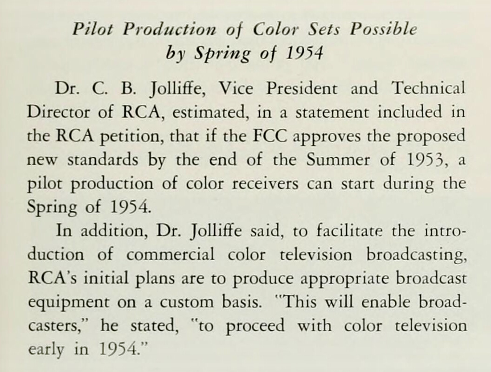
Courtesy Radio Age January 1953
Posted June 9, 2023
Here, an excerpt from The Sarnoff Collection at TVNJ which describes the RCA CT100 as a pilot run set to prove that color receivers could be manufactured on a large scale. With production ending May, 1954 and 4000 CT100’s delivered by May, 1954, the set was not “the first mass produced” color television as reported in other publications. It can only be claimed that RCA manufactured the largest number of color sets in 1954. Note: The below clip (1953) is incorrect because the CT-100 did not go on sale until April, 1954. Read the full article here.

Posted October 31, 2023
Let’s add clarity.
By October 31, 1954, a total of 17,445 color receivers were produced according to RETMA.

By year end 1954, according to Sylvania research director, Frank Mansfield, 10,000 color sets sold and in use.

RETMA reports a total of *25,000 color sets were manufactured, year ending 1954.

*Authors note: During the first six months of 1954, the principal manufacturers of color television receivers were RCA, Westinghouse and Admiral. By August, 1954, the 15 inch color sets were no longer in production and Motorola, Westinghouse and others began production of 19 inch colors receivers and in December, 1954, RCA, Admiral and others began production of 21 inch color receivers. This accounts for the higher 25.000 manufacturing figure and only about 10,000 color receivers were in use with a percentage of these sets used for professional and commercial purposes.


March 7, 1955


This article lowered total color TV production for 1954 from 25000 to 21500 sets. This includes all 15, 19 and 21 inch color sets manufactured in 1954.


Recollection.


We were searching the old posts at the VideoKarma forums and found this posting from Roger Dreyfoos.
”Yesterday, we went to a Best Buy store to see a Samsung 3-D LCD model set up for demonstration. It actually brought back a memory from 1954, of our dad taking us downtown to see a COLOR TV (Westinghouse) set up in the window of a department store – probably the only color TV in Wichita – other than a broadcast monitor back at the transmitter. We were part of a small crowd straining to see the washed out picture (summertime, about 7PM) of Ed Sullivan’s Toast of the Town show from the local CBS affiliate, KTVH. If that was color TV then that demo would never sell any.”
MAY 5, 2018
We just acquired a Westinghouse H840CK15 at the annual Early Television Convention auction held on May 5, 2018. We know absolutely nothing about the history or prior ownership of this set. If anyone that attended the convention knows something I’d appreciate hearing from you. The auction was streamed live on YouTube and the below photo captures the auctioneer (in black jacket and cap) at the precise moment the hammer fell, SOLD! We we’re thrilled, as this set escaped us five years earlier.

This photo, courtesy of Wayne Bretl at the convention.

The set was described as having an “excellent” 15GP22 CRT with a complete, but unknown chassis condition. Three photos of the flyback area look clean. As always, tap on image for larger size.


The set will be crated with five layers of protection. I asked Larry at the museum to make sure the chassis’s bolt are tight and secure. When the 21CT55 arrived, we found two bolts on the cabinet floor. No damage occurred because the set was immobilized in such a way that the set could not move within the crate. We are doing the same for the Westinghouse with a “floating” isolation platform on a pallet.
This time I won’t have the pleasure of uncrating the Westinghouse, instead, it’s going directly to Mike’s ranch about 150 miles Northwest of me. That will save him three trips to my home. Mike will be doing the restoration as I do not have the skills to work on a television of this complexity.
A word about Mike Doyle, a Videokarma member.

Mike Doyle and son.
I met Mike in 2011 on EBay after calling his phone number to talk about a recapped Sony Micro set he worked on and which I purchased. His next project for me was bringing back to life a SONY TV 8-301W, followed by a RCA 21CT55 and a RCA CTC-7.
Mike started out his career as a television repairman. Over the decades he worked on well over a thousand televisions, both color and black and white of all brands. He told me he has repaired over 500 flybacks and never had one fail within their normal lifetimes.
Mike moved on and began work for CalTech. He was an engineer on the team that designed the prototype Hubble space telescope. He worked on the “4 shooter” project. Later, he worked at the Mt. Palomar Obseratory in Southern California. He also taught electrical theory to his students at Palomar Journal College.
Tap on images.


FRIDAY, FEBRUARY 1, 2008
Say goodbye to Palomar
After a combined 47 years of service to the observatory Mike and Barbara Doyle are saying goodbye to Palomar. Mike served mostly as an electronic technician before moving up to assistant superintendent. During my brief term of service here I have known him to be a dedicated and vital part of the Palomar team. He has provided great support and advice to myself and the observatory’s public outreach program.
Barbara has worked in the observatory’s accommodations for the astronomers, known as the Monastery, and also has been the powerhouse behind the observatory’s gift shop. She has professionally greeted and explained the observatory to many thousands of visitors over the years.
I join the entire Palomar staff and our team of docents in wishing them well in their new venture. They will certainly be missed but their hard work, commitment to doing things right and friendship will linger with us for some time to come.

Mike is now enjoying his retirement with his wife on their ranch. He also collects vintage television and a few of his sets can be seen on the “ViewersTV page. We have high confidence in Mike’s abilities to restore this set. Still, we will undoubtably reach out to the vast data bank of information possessed by the members of the VideoKarma forums. More to come.
Update, July 11, 2018
After a long delay, the Westinghouse H840CK15 is finally on its way to Mike in Arizona. Here you see the set crated. The only way to go when shipping 2000 miles.


Update, July 20, 2018
The Westinghouse arrived at Mike’s place today. Below, the meeting and unloading operation.
The meeting at Exit 20 Interstate 40.
Pix 1 and 2. A smooth transfer from the FedEx truck to my truck.
Pix 3 loaded and strapped in and ready for the trip on 12 miles of dirt road. SLOW
Pix 4 Looking East on Fireside Drive. Home is 8 miles ahead.


Pix 5 A 1954 loaded in the back of a 1974
Pix’s 6 and 7 Rigged and ready to unload. This is really a lot safer than it looks.
Pix 8 Safe in the shop!


Update, July 21, 2018
Uncrating completed. Good news, no apparent visual damage. We won’t know more until basic testing. Full recap will be done prior to attempting to light the tube. More photos to come.
Update, August 7, 2018, Day 1
The cabinet is in dire need of restoration as seen below. Mike will bring the cabinet to me for refinishing. The chassis and CRT will stay with Mike for the electrical restoration. Tap any image to open the image carousel. Tap the full resolution icon for full size.


From Mike: “OK, here are the pictures of how I tested the CRT. Picture #1 is before anything is disturbed. Note that the screw on the right side of the centering coils was found below resting on the chassis. The one on the left (shown removed) by me.
Picture #2 centering Coils removed.
Picture #3 CRT neck cleaned of dust and ?
Picture #4 My universal cable that I made for my tester. Wires for Filament 1, Filament 2, Cathode, Grid 1 and Grid 2. These are needed for the test of the individual guns. Filament voltage is 6.3 Volts.
Picture 5 Red gun hookup.
Picture 6 Green gun hookup
Picture 7 Blue gun hookup.
The numbers were RED .825
Green .6 and
Blue .9.
A bit weaker than I had hoped. But the CRT is alive. Time will tell later down the road. A side note: The getter flashes look really good. Tap any image for an enlargement.


Authors note. We can’t understand the manufacturers reasoning for placing the hue control at the rear of the cabinet. What were they thinking? It’s attached to a long cable, so it may be possible to reroute the cable and control to the pencil box. More to come.
UPDATE, AUGUST 10, 2018, Day 10
From Mike:
Tonight I began the chassis removal process. I am collecting photos which will come later. I was very disturbed to discover that there were NO CHASSIS BOLTS at all holding the main chassis to the cabinet.
The chassis serial number is on a tag glued to the high voltage cage and it appears to be ME000147
I take that to be the 147th one produced. The ME is likely a location code of where it was built. Any ideas?
No serial numbers on the crt neck or socket but the code date (which is visible in your picture) is 4-13.
I take that to be the 13th week of 1954 which likely makes this the original crt.
Author: I wanted to make sure the chassis bolts were tightened and that they be checked prior to crating. I was assured this would be done. Very disappointing!
Possibly ME stands for Metuchen, NJ. Where the first sets went into production.
According to Marlin Mackey’s site, the set serial numbers don’t jive with the chassis numbers. An example: Television serial number MW006012, chassis number ME000812.
Thanks for the numbers, I agree. More to come.
UPDATE, August 12, 2018, Day 12
From Mike. OK, onward to removing the chassis and crt. This will be sent over a few emails due to the number of pictures.
Pictures 1 and 2 Front panels and knobs being removed.
Picture 3 Broken knob (the white one). Not sure of its function just yet.
Picture 4 Chassis on the bench. Note: there were NO chassis bolts holding the main chassis to the cabinet. The power supply chassis is mounted in the lower part of the cabinet and it will be removed soon.
Picture 5 and 6 show magnetic shield mis-alignment bottom and then top. I believe when this piece is properly installed it should mate nicely with the other parts.
Picture 7 These pieces fell out from under the chassis as I removed it from the cabinet. One screw that I might likely find the place for later, the second looks like a tuning slug from one of the tuned transformers. (the next picture shows where this possibly came from). And then, what looks like a broken tuning slug core from some tuned transformer.
Picture 8 a tuned transformer with seemingly a missing tuning screw. The core piece may be inside the transformer.
Picture 9 Chassis top left.
Picture 10 Degassing coil plug.
Picture 11 and 12 Disconnecting the High Voltage connector.
Picture 13 Blocking the face end of the crt before removing screws. This insures minimum loading on the neck of the tube as the screws are removed.
Picture 14 Removing the necessary 3 screws on each side to unmount the crt from the chassis.
Picture 15 CRT removed.
Picture 16 CRT on bench. The tube will be boxed and placed in another building with my other CRT’s until I am ready for it later in the restoration process.
Picture 17 Serious issues with the quality of the aquadag on the CRT.
Picture 18 These flakes of “DAG” were found on the chassis after the crt was removed. I guess it’s a good thing that I purchased a supply of aquadag liquid from Scott Avitt before he closed up Hawkeye. This issue, I’m sure, will be a very easy part of the restoration process.
Picture 19 The chassis bottom.
Thus far, I have been doing some thinking on how this restoration will go. I will be doing this one a lot differently than ever before. Most of the repairs will be done without a crt at all and using only test equipment to breath life back in to the individual circuits. That way the CRT stays “safe” until I am ready for it. I may use a monochrome crt mounted to the chassis for some of the testing process. The signals from the individual circuits can then be patched in to the monochrome gun one at a time so the quality of the images can be seen as needed. This way, the Luminance and Chrominance signals can be evaluated without the use of the 15EGP22 being in the set.
Let the games begin.
Mike


Good Afternoon Mike,
I have all 19 photos. Thank you. Breathed a sigh of relief after reading your last comment about the dag.
Sound like an excellent plan. Great idea to remove the “beast” from the chassis to allow easier serviceing.
Marshall
As always, tap on any image to open the image carousel. Tap icon again for full resolution images
UPDATE, AUGUST 13, 2018, Day 13
From Mike: I have been studying the Westinghouse documents and learned that the degaussing ring on the front of the crt is in fact the opposite. Interesting to me, it is a gaussing coil that actually sets up a magnetic field that is adjustable, at the faceplate of the tube. So, I think we can change the wording on the page. IF I learn differently I will let you know. And again, Let the games begin. This will likely be the biggest accomplishment yet for me in my restoration projects. I remain optimistic. And it looks like I have a lot of parts to order for this one.
A piece of the wiring fell out of the high voltage cage when I set the chassis on the bench. It looks like a wire from one of the filament leads to a high voltage rectifier but I have yet to figure it out for sure. Also, I noticed that the metal cover is missing from the high voltage cage on the right side. This will be easy to make but it will not be of the original material unless I can find copper clad of that size locally. Not a big deal, just an observation that I will have to deal with. I suspect that a tech has left it off to give more cooling to the flyback. Maybe not a bad idea to leave it off but we can discuss that sometime.
Author:
I’d like to point out in pix# 2, a user “convergence” control. Pix #8, notice the cable leading to rear mounted hue control. I’d like to rig the cable forward and exiting at the bottom of the cabinet. In this way I can actually see the adjustments on the screen. The mirror idea seems ridiculous on a restored set. For purists, we can easily restore to it’s original position. Pix #13, blocking while releasing tension loading.
We shall see as the restoration progress’s.
UPDATE, AUGUST 26, 2018, Day 26
From Mike: Greetings Marshall. We are packing up the cabinet and brass pieces today. We should leave here by around 8:00 on Monday morning and see you by 11:00 or so. FYI, in case you want to research it, and in case we need it later, the Westinghouse part number for the flyback is:
V-12977-C1
We never know what might show up out there and it would be a very, very good thing to have a spare, if possible. Before I can do anything on this set I will be building a bigger workbench. So as soon as the cabinet is in your hands I will have the space to press on. I have done some visual examination especially around the high voltage and flyback area and learned that the wiring around all of the rectifier sockets is very poor so that will have to be addressed early on in the restoration stage, after I get the power supply somewhat working. Also, my plan is to eliminate the filament wiring for the H.V. rectifiers and convert them from the original 3A3 tubes to solid state devices such as ECG508 Sylvania/Phillips devices. I am on a mission to find QTY 3 of those now. The focus rectifier tube will also be replaced with a solid state device of some type as well. By doing these modifications it not only eliminates vacuum tube heat, it also eliminates a lot of unnecessary wiring that has the potential to cause arcing which of course is very undesirable.
See you tomorrow.
Author: Okay, see you tomorrow. We will place the cabinet in the garage as I will be taking it to our community wood shop for refinishing. I will post this in VK in hopes of a lead. Sad about Senator McCain.
In the garage today. Soon, I will be taking the cabinet to our community workshop for refinishing.


We found a cabinet number and some sort of serial numbers on the tag glued to the inside of the cabinet.


SEPTEMBER 6, 2018, Day 37
Due to the enormous Westinghouse chassis, Mike rebuilt his work bench to accommodate it. Here you see the main and sub chassis. I’ve seen Mike’s test equipment which are not shown in these photos, and it looks like these photos were taken shortly after completion of the bench. Power supply parts have been ordered and the restoration begins.
From Mike:
“The “beginning”. The bench is complete with power strip and overhead shelf for test equipment. The giant color chassis fits the new bench well. I noticed that the copper plate cover that I retrieved from the cabinet is not the one that I thought it was. It is actually the one for the bottom of the flyback area so we still need to find out if the original is available from ETF. I have allowed room on the new bench for yet another “jig tube” for when I get serious about testing the operation of the chassis after I get the power supply and sweep circuits going. I will be using the oscilloscope for much of the early testing of the power supply and sweep circuits. And I will pay especially close attention to safety of the flyback transformer.
Mike”
Author: I spoke with Steve and the missing panel from the flyback box was not left behind at the ETF.
Tap on images for full view.


UPDATE, SEPTEMBER 13, 2018, Day 44
Nothing Major.
From Mike: I hooked up a variac to the chassis a couple of days ago and started it at 25 volts. Then about 5 minutes later I set it to 50 volts and watched the power supply tubes start conducting. They are a set of 5U4’s and there are 3 of them for the different voltages that form the power supply. The purpose of this exercise is to determine the exact running voltages that were originally designed in to the system using the 5U4 vacuum tubes. I got the voltage up to the nominal 120 VAC after many small steps and I got smoke from one of the resistors in the power supply. NOT a surprise at all. The reason for the smoke is an “open” capacitor in the power supply section of the circuitry. As it turns out, Westinghouse made this chassis such that the “power supply” is not limited to the chassis below in the cabinet. That chassis is only the first stages of the supply, which is rectification and “preliminary” filtering of the pulsating DC that is created from the rectifier tubes. There are a number of places in the chassis where they placed “redundancy” filtering to make sure that he DC was always pure everywhere in the system. I will be doing a lot of re-capping as a result of diagnostics in an effort to methodically bring this thing back to life. Once I determine what the “actual” operating voltages are, I will be installing solid state rectifiers in place of the 5U4’s and then applying resistance values in the system to reproduce the proper and “original” DC supply values. This placing of resistance values is necessary due to the fact that the solid state rectifiers are much more efficient than the original 5U4’s that are very inefficient by comparison.
I just placed a very large order for capacitors so I can press on to the next phases.
Regards, Mike.
Author: No photos on this one.
UPDATE, SEPTEMBER 14, 2018, Day 45
I live in a retirement community which has its own wood and metal shop. Today friends helped move the Westinghouse cabinet and we drove it to the wood shop.


UPDATE, SEPTEMBER 24, 2018, Day 55
Greetings Marshall. I have recapped the main power supply and verified the design voltages as they are at this time. They will likely be lower during later tests since I have the sweep circuits disabled for the preliminary testing. For the foreseeable future, and maybe permanently, I will be leaving the original design in place with the 5U4 tubes. We will see how that goes later. OK, now for the pictures.
Picture #1 shows a couple of caps replaced but except for that, the chassis is as I received it. Mostly “untouched” which is how I like to get them. These caps were actually broken off at the terminals so I went ahead and replaced them. They can be seen as orange and brown components at the lower left.
Picture #2 is the main power supply chassis before re-capping.
Picture #3 is the main power supply chassis after re-capping.
Picture #4 shows my oscilloscope screen showing the waveform of the grid drive to the Horizontal Output Tubes (6BG6’s).
This tells me that the horizontal oscillator is running and the drive signal to those tubes is good even before recapping. This signal on the scope is about 200V P-P and the Photofact refers it to be 150 V P-P. Given the fact that most of the running voltages are a bit high right now because I have the main power to the sweep circuits disabled, it is expected that the signal would be a bit high. This is good at this point.
This step is important because it means now, that I can do some testing of the flyback transformer. It won’t tell me everything about it, but it will tell me a lot.
Mike.
Tap images fo full view.


UPDATE, OCTOBER 2, 2018, Day 63
Hi Marshall. I spent some time this evening working on the distressed wiring in the High Voltage cage. The purpose of the “wiring fix” is to allow me to test the circuit as designed before I make any modifications during the restoration process. The wiring fix involved “putting back” some of the wires that had simply fallen off of places from age and from the “trip”. Anyway, I am now able to confirm that the flyback is “alive” at least to the point of generating High Voltage. I got 20 KV on the final anode lead with the regulation tube disconnected. Obviously this is a critical thing to verify early on in the restoration process. It is now time to test and replace tubes and then look at a bunch of other signals with the oscilloscope as we proceed. It is also time to start replacing a lot more capacitors. At some point, probably very soon in the process, I will return to the High Voltage section and do some more work there. But this test verifies a lot of components like the “doorknob” capacitors and insulators in the High Voltage section.
YAY!!
Mike
Author: Great news! I think the nominal ultor voltage for this set is 19.5 KV?
Mike: Yes, that is what the nominal HV should be at the 2nd anode. The actual HV generated should be, I think, more like 22.5kv or more. This is due to the function of the 6BK4 Shunt Regulator that keeps the regulated voltage at the 2nd anode at roughly 20KV at all brightness levels. The overhead voltage is so the shunt regulator can do that job at different beam currents. I made this test with no shunt regulation at all. I believe that the initial HV will come up quite a bit after some recapping and tube replacements like the 6BG6 Horizontal output tubes. I still have to go through the tubes and test them all. But this tells me that it is now OK to move forward with the whole project
UPDATE, OCTOBER 3, 2018, Day 64
Let’s add clarity
OK. I have studied 3 different schematics.
The Photofact for CT100 RCA calls for a primary transformer DC resistance of 1200 OHMS There are 2 secondaries. Secondary #1 calls for 1800 OHMS and secondary #2 calls for 7200 OHMS.
The Photofact for Westinghouse chassis calls for Primary DC resistance of 1000 OHMS. Secondary #1 is 3200 OHMS and secondary #2 is 3800 OHMS.
Westinghouse factory schematics calls for Primary DC resistance of 1000 OHMS. Secondary #1 is 1350 OHMS and secondary #2 is 375 OHMS.
I realize that these are DC resistance values and the actual IMPEDANCE for the components is not really called out on the schematic. BUT, these numbers should agree to a much greater degree of precision before I believe that the RCA part is the same as the Westinghouse.
I ran out of time tonight but I will be doing DC resistance checks tomorrow night in an effort to sort this out.
Stay tuned!
Mike.
UPDATE, OCTOBER 11, 2018, Day 72
Unfortunately, the VDC transformer tested open in both secondaries. We are told that the transformer we need has been rebuilt in numbers. This rebuilt transformer, Westinghouse part number 241T1 has been installed successfully in RCA, Westinghouse and other 15 inch early color sets.
According to VideoKarma member Bob Galanter, “In the CT100, the transformer is “potted” in a 5 sided metal box that bolts onto the back of the HV cage. In the Westy, it is just an open frame transformer similar in appearance to a regular vertical output trans.”
Author: We wonder why RCA took the trouble to “box” the transformer and Westinghouse did not?
Mike explains: “RCA recognized possible faults in the wire insulation and maybe they anticipated the failures. The physical construction difference is interesting. However, the real difference to me is that the “impedances” are different. John (Folsom) explains that his aftermarket transformer was custom built as an “average” impedance match to satisfy both RCA and Westinghouse models. The impedance match is critical for proper operation of convergence and it is also critical to surrounding components in the sweep circuits. Mostly for proper “resonance”.
Thankfully we found a source, ordered the part and it’s on the way back to us. Recapping continues with bad resistors found along the way.
UPDATE, NOVEMBER 14, 2018, Day 106
After a brief hiatus, recapping continues. Under the RGB Adders and amp circuits was a big resistance array mounted to terminal strips. This bank of parts prohibits access to the bottom of the chassis where the RGB adders and amp circuits are. After some study I determined that I can disconnect 4 wires that were going from the resistance array down to the RGB circuits and then remove the screws on the mounting plate allowing the entire array to “fold away” and “down” from the part of the chassis that I needed access to.
Picture #1 The new VDC transformer mounted but not yet wired.
Picture #2 Shows my “impossible access” to the capacitors that need replacing.
Picture #3 Shows the assembly pulled away and folded down after disconnecting the 4 wires. Full access to the components is now possible.
Picture #4 All new caps and some new resistors installed.
Picture #5 The assembly re-installed and the wires re-connected.
Cheers, Mike


.
UPDATE, NOVEMBER 16, 2018, DAY 108
The cabinet restoration begins.


UPDATE, November 27, 2018, DAY 119
Good progress on the cabinet restoration. All that remains is to detail the channel selector and volume control knobs. They are brass.


UPDATE, NOVEMBER 28, 2018, DAY 120
The cabinet restoration completed and back home, waiting for it’s chassis. Mid-Century styling at its best. Tap on images for full resolution.


UPDATE, December 4, 2018, Day 126.
The Process continues ….
Greetings Marshall. The process continues. There are 2 more electrolytic “cans” that I need to replace and the screen grid resistor for the horizontal output tubes that is chassis mounted is also in need of replacement. These types of resistors are obsolete so I will be mounting terminal strips to the chassis where the original resistor is in order to make that repair. Also, the modification to the ON/OFF switch with the added relay will be necessary and I need to find one of those relays before I can do that mod. I will be servicing the tuner also, while the chassis is in this position on the bench. I hope to start firing things up within the next month or so in order to determine the condition of things. So far, a lot of capacitors and resistors have been replaced, all in hopes of a positive outcome. When I am finished with the “bottom” of the chassis, at least for now, I will begin the component replacements on the top. Some of those are in the High Voltage cage and there are several others in different circuits that I need to explore. I have attached 2 pictures. The first one is an image of the parts that I have replaced so far. The second is the bottom of the chassis showing the new parts. The image can be compared with the original that I sent previously before the restoration was started.
Cheers, Mike
Author: 104 parts replaced.

The beginning, August 12, 2018.

Now, December 4, 2018.

UPDATE, DECEMBER 9, 2018, DAY 131
Progress continues. There was a power resistor in the screen grid section of the horizontal output tubes that showed very intermittent results with the ohm meter test. It had to be replaced. The original was a chassis mount which is unobtainable. I replaced it with a modern day film type flameproof resistor and it is mounted on to terminal strips. Also, today I finished wiring in the new Vertical Dynamic Convergence transformer. It was necessary to extend the leads in order to make them fit to the proper terminals under the chassis. I also installed a plastic grommet where the wires feed through to the bottom of the chassis from the top. Then I used electronic lacing tape to further strain relief the wires so they are out of the way and close to the top of the chassis. During the process, I replaced the two 6 KV capacitors that are part of the tuning circuits for the convergence adjustments. The wiring from the techs before me was a real mess. I’m sure that if you compare the original bottom view, you will see what I mean. The following pictures are:
1. The modified screen resistor. The one on the towel in the foreground is the one that was removed.
2. The underside showing the plastic grommet where the high voltage wires feed through from the new transformer. One wire is already connected here.
3. The wires after installation and the electronic lacing tape (double wrapped) to secure the wires to the chassis, out of the way.
4. The finished transformer wiring with the newly installed 6 KV capacitors.
4. The finished transformer wiring with the newly installed 6 KV capacitors.
.


UPDATE, DECEMBER 20, 2018, DAY 142
Greetings and Merry Christmas Marshall and family.
The relay that takes the load off the main on/off switch has been installed. The relay is installed on the top of the power supply chassis. There was absolutely no room whatsoever on the bottom of the main chassis and there was plenty of room on the power supply chassis. The brown wire is the one that brings in the power from the main interlock which exists on the main chassis. There were no spare connections available on the original plug assembly. The brown wire has its own separate connecting plug. 3 photos show the placement of the new component on the power supply chassis. Next is the task of removing the tuner, rebuilding it and re-installing it. Then we can get on with powering up the chassis with the sweep circuits disabled. This will allow testing of the tuner, I.F. strip, sync circuits, video amplifiers and hopefully, more.
Cheers, Mike
Author: I’m happy Mike is once again doing this modification. He installed a relay in our 21CT55. In our home whith many appliances running at the same time, if I switch on the 21CT55, I see the lights dim briefly. A lot of current passes through the relay to the power switch. Merry Christmas Mike and VK members.


UPDATE, DECEMBER 30, 2018, DAY 152
Greetings Marshall. We are finished with the bottom of the chassis, at least FOR NOW. Picture #1 is the top of the chassis again, and it shows nice clean capacitor cans that have been replaced. The rest of it still needs a lot of cleaning and yet, some more components replaced. For now, it is time to rebuild the tuner since the lubricants have long ago turned to something more like plastic rather than grease or oil. But first, I have snapped a picture of the “HUE” control that you speak of and have asked it to be moved to the front of the chassis. This is not going to happen. The HUE control is NOT a POT. It is a coil. There is a flexible cable that is manufactured to fit the top of the slug of the coil and that is their method of changing the phase relationship of the colors. I do not see a “good” way to move this control. It would be problematic since the controls on the front panel are all below the “plane” of the chassis. Anyway, Picture #1 shows this issue. Picture #2 shows the chassis with the nice new electrolytic cans and a “somewhat” dirty chassis. This will be cleaned up a bit during the next restoration phases.
Picture #3 is before the tuner removal.
Picture #4 is the tuner removed.
Picture #5 is the cover removed and you can now see the corroded condition of the contacts on the channel elements.
Picture #6 Channel strips removed.
Picture #7 Inside tuner main shaft removed.
Picture #8 Tuner contacts and body cleaned. And all resistance values checked.
Picture #9 Main shaft and Fine Tuning shaft before cleaning.
Picture #10 Fine tuning shaft, contact spring and detent wheel before cleaning.
Picture #11 Parts ready for re-assembly.
Picture #11 Parts ready for re-assembly.
Picture #12 Drum and detent installed.
Picture #13. All strips re-installed, the cover is on and the tuner is ready to re-install.
Picture #13. All strips re-installed, the cover is on and the tuner is ready to re-install.
Tap on images to enlarge.


UPDATE, JANUARY 18, 2019, DAY 171
Hi Marshall. Now that I have things squared away on the *“mountain tops”*, I am back to the Westy. During the dismantling of the set you might remember that I mentioned a powdered iron core slug that I found in the ventilating screen after removing the chassis. Well, I FOUND OUT where it came from. It came from the Hue control coil (Burst amplifier). I will need to remove the transformer and likely manufacture a new slug assembly for it. The pictures are as follows. 1) and 2) The broken piece that I found. 3) and 4) Shows more cleanup of the top part of the chassis. The deflection yoke has been removed so it can be cleaned and serviced separately. There is still one large axial type capacitor that I need to find and it is seen just above the white wires from the new VDC transformer. 5) and 6) shows the burst amp transformer bottom view and top view that I will need to remove in order to rebuild the iron core that is broken. The 2 horizontal output tubes (6BG6) are separate manufacturers and the date codes are many years apart and they should be replaced with a matched pair. Also, there are 2 damper tubes which by design are 6AX4 type. These are really tubes from the “black and white days” and that is why they used 2 in parallel instead of the usual 1. One has been replaced with a 6AU4 type , which is the “stronger” version of the 6AX4 and was designed for use in the newer color sets that were made after the Westy. Bottom line is, these should also be replaced with a matched pair of 6AU4. I will be purchasing these for replacements before I fire up the chassis to do any further sweep circuit testing. My next steps will be to “look” into the high voltage section and do a lot of work in there. I have already purch ased a new matched set of 3 high voltage rectifier tubes for that section. I originally was going to convert these to solid state however I have changed my course of action on that decision for a number of reasons.
Cheers, Mike
* Author: Servicing the various communication repeaters in Mohave County, Arizona.


February 1, 2019, Day 185
Next! The high voltage cage. I have received the matched pair of 6BG6 JAN (joint army navy) mil spec tubes for the horizontal output stage of the sweep circuit. I still need to find a nice pair of 6AU4 damper tubes to compliment the output tubes but the damper tubes are not as critical as the outputs as far as “matched pairs” go. The focus rectifier tube will be replaced with a solid state selenium type such as what was used in the CTC15 RCA sets. I have purchased a matched set of qty 3 (1B3) rectifier tubes to replace the High Voltage rectifier/tripler set. I will be replacing the capacitors in the high voltage cage and I will be replacing the resistors with modern type film resistors as well. After these restoration procedures I will be ready to start powering up the chassis with the sweep circuits disabled in order to test the individual circuits. I will use an oscilloscope for that process. The signal source will be either antenna TV signals or crosshatch signals from a color generator.
Cheers, Mike.


UPDATE, FEBRUARY 24, 2019, DAY 2019.
From Mike: “Hi Marshall. I have reached a “pause” in the restoration for now. I got in to the high voltage cage finally and one of the things I discovered was a faulty DC Dynamic Convergence Potentiometer. It is a 50 MEGOHM beast of a pot and of course, it has high voltage on it so it has to be the right part for the job. After doing a bit of research myself, I once again, contacted John Folsom and Bob Galanter. Bob did some research himself after telling me that he had not started his restore on the Westy at his place. He indicated that he will likely need the same component when the time comes for his work. And after my explanation of the failure mode, we agreed that this is a definite “weak spot”.He found a place in the UK that makes and sells a 33 Megohm high voltage Pot so I have ordered 10 of them. The cost was not much and I figure I can share the stock with others if necessary. The idea is to add 10 Megohms to each side of the 33 Megohm pot that I am purchasing and hope to find the “center” of the control at “good” convergence. Some mechanical modifications may also be necessary. Let’s hope this works.
So, here we goOOOOO.
We are truly going where NO MAN HAS GONE BEFORE.
Cheers, Mike.”
Author: Well the Britt lead turned out to be a bust. No response.
From Mike: “Greetings Marshall. In communicating with Bob Galanter, he sent me a link to a company in the U.K. They have been no help at all. I get a message from them after the “cart checkout” that my address is invalid. I sent the company an email and asked them what I need to do to place the order. That was 3 days ago. I have not heard a word. So that is not looking good.
So, I started thinking real hard again, as I do when I am “stuck”. And my thoughts took me in to my earlier days of television repair. By earlier, I mean the 70’s. I remembered that the age of solid state was booming and that the high voltage systems had changed dramatically from the 60’s and earlier. I then remembered that those sets from the 70’s often times implemented ceramic substrate focus controls. BINGO. I did some searches using the simple words “RCA focus control” and “Zenith focus control”. And where did I end up, but ebay with a listing for 40 megohm ceramic substrate focus control part number 63-7145. This part, I am almost certain, will work in the position for the Dynamic Convergence Pot which is designated 50 megohms. A very easy adaptation, I think. Let’s not get too excited yet, but I bought it and it should arrive in a few days. I have also purchased $$ a number of high voltage resistors of different values to aid me in rebuilding the high voltage circuits where these pots go. I am also going to replace the focus control, although it checks reasonably good. It is buried behind the Convergence pot so I should go ahead and replace it if I can find something of the 70’s vintage in the form of a 5 megohm for that position. I have also purchased a 5 megohm 2 watt pot that I think I can modify in case I don’t find the real thing in ceramic so I think I have this covered. I am definitely “on” to something here, though, by remembering my days before Palomar. I have not discussed this with Bob yet. I want to get it in the mail and make sure it will work first. I will have to invent a new mounting scheme, but that is really no surprise. The fact that I was able to find ceramic 40 megohm pot for the convergence is a really good thing if it works. It will mean that I can pass this information on to the other people that are working on these sets.
Cheers, and onward!
Mike”
From Mike today: “Greetings Marshall. This is just an update on the attempt to find the parts I need to continue. I received a Zenith component and an RCA component yesterday. I found these on ebay. Neither one is a perfect part for the circuit but they are close. They might be close enough but I won’t know until I adapt them in to the chassis and “fire” things up. I am also waiting for one more possible candidate for the convergence pot which is a mid 80s RCA part. When it comes, I will evaluate that one. I shared my “find” of the RCA part that I received yesterday with Bob and he was very optimistic (as I am) that it will work. He was very happy since this may actually help him with his project as well. I have also ordered an assortment of High Voltage resistors of different values which will help me adapt the pots to the circuit. I expect the other RCA part to show up on Monday. I am hopeful that it may possibly be a “better fit for the circuit. I will then have 3 choices to choose from for the next steps. All of this part of the restoration takes place inside the High Voltage cage where the flyback is, so I need to be very careful about my choices of components and the placement of them.
Stay warm.
We keep a wood fire going in the fire place this time of year.
Cheers, Mike”
Author: We are experiencing unusually cold weather near the Phoenix Valley. It snowed in North Scottsdale yesterday!
UPDATE, FEBRUARY 26, 2019, DAY 210.
Greetings. I will be moving forward on a plan to install a new Focus pot and a new Convergence pot into the High Voltage cage. My exact plan is not yet in place, but it is close. The following pictures show preliminary steps for the process.
Pix. 1 New caps installed in high voltage cage.
Pix. 2 The old Focus and Convergence pots before removal.
Pix. 3 The old shaft drive system using slots in the fiberglass shafts where they mate with the old pot shafts.
Pix. 4 The slotted shafts that will need to be fitted with shims so that they will mate with the new pots later.
Pix. 5 The shafts with a piece of PVC sheet stock that will be used to make the shims.
Pix. 6 Shafts and new shims.
Pix. 7 Shims installed.
Cheers, Mike


UPDATE, MARCH 6, 2019, DAY 218
Greetings. While I am waiting for more parts for the high voltage cage rebuild, I have taken a step back in order to repair the Burst Amp coil that I previously reported to be broken. I found the iron core in the bottom of the cabinet when I removed the chassis a few months ago. I later learned where the core came from. The powdered iron core was mostly intact and all that was needed was JB Weld Epoxy, and then fine sanding in order to restore its original cylindrical shape. The JB weld worked equally as well on the coil form repair.
Pict. #1 Broken coil assembly
Pict #2 Broken core and bent lead screw
Pict #3 Broken coil form
Pict #4 Repaired and straightened iron core and coil.
Pict #5 The finished coil re-assembled and ready to install in to the chassis
The high voltage cage rebuild will be completed next.
Cheers, Mike


UPDATE, MARCH 12, 2019, DAY 224
The surgery continues.
Greetings. The first “pass” at the high voltage cage is finished. I say “first pass” because the convergence pot issues are still experimental and I will likely need to make some component adjustments of the high voltage resistors that form the divider circuit on either side of the new pot in order to bring the convergence in to range. The reason for this is that the original pot is 60 megohm and the new circuit with the Zenith 63-7145 only has a swing range of 20 megohm. Some resistance is already built in to the Zenith part so that has to be considered in the calculations. I hope that convergence can be achieved within this new range. If not then I will be experimenting with the values a bit. The important thing that I need to adhere to is the original divided resistance value of the circuit since the 3 circuits (Focus, High Voltage Regulation, and Convergence) all interact a small amount by existence of these resistance values. The total value that I removed was between 230 and 240 megohms. My new value across the divided network is 219 megohms and there is a 7 megohm resistance built in to the new pot at the swing arm so that introduces some need for experimentation which I hope is soon to come. Also, I will soon need to address the issues with the crt socket. I have found a vendor but they are not responding to my queries about availability and cost. I may have to attempt a rebuild of the original socket.
Pict. #1 Old convergence pot left and Zenith 63-7145 right, mounted to the original bakelite panel with nylon screws and plates.
Pict. #2 The new circuit with experimental values shown.
Pict. #3 The original Focus pot which cleaned up nicely and seems to be OK. New wiring to the pot along with new capacitor (yellow) and High voltage 8 megohm resistor (blue) hard to see behind the cap.
Pict. #4 High Voltage cage with some, not all new wiring is complete. Note that the original 1AX2B focus rectifier tube is now solid state. (white stick near center). And the control shaft coupling to the new convergence pot was accomplished with a high quality piece of silcone rubber tubing. (lower right, orange) . And finally, all 3 of the H.V. rectifier tubes are replaced with a matched set of JAN Mil. spec 1B3’s.
Cheers, Mike


UPDATE, MARCH 21, 2019, DAY 233
From Mike: Here is the latest. I have received word from Steve McVoy at ETF that he has NOS sockets for 15GP22 crt’s. He is sending me one and only asking for a donation to ETF of $20.00. I sent him $25 as a donation and the socket should be here soon. The recent action on the restoration is that I installed a line fuse on the primary of the power transformer (where it belongs). The fuse is located on the top of the chassis next to the horizontal output tube sockets. The other progress is the new covers for the deflection yoke. I purchased 2 sheets of ABS plastic 1/16 inch thick to make the new covers.
Picture 1. The newly installed line fuse.
Picture 2. The ABS sheets.
Picture 3. The old yoke cover repair.
Picture 4. The old covers removed.
Picture 5. New ABS parts.
Pictures 6,7 New parts installed with nylon screws and spacers.
Cheers, Mike


APRIL 7, 2019, DAY 250
From Mike: Greetings. The socket has arrived from the Early Television Foundation. A real nice, high quality socket and a bag full of connector pins. So, I have to find the proper wires in order to complete that task. I could just use any wire and any color, but that is just not my way. The wires need to be the proper color and stripes for their function of the signals. It makes troubleshooting a lot easier in the event that it becomes necessary, and it retains the original equipment manufactured specifications.
I have assembled the new crt socket. It is ready to install.
Picture 1. The “kit”
Picture 2 and 3. The assembled socket with all new wires.
Cheers, Mike


UPDATE, APRIL 9, 2019, DAY 252
We have video! First images.
From Mike: “Hi Marshall. The jigging process went as planned. The focus voltage is missing and I’m not sure why just yet. I ran out of time tonight. There is a LOT of GOOD NEWS though. The image is there. It is in good vertical and horizontal lock so the sync circuits are working and the chassis is actually sweeping a raster. With no focus voltage, the images are very blurry. I will sort that out when I return from my vacation. The other good news, is that the convergence voltage (on the wire that is not connected to anything), is swinging from 5 KV to 8 KV with the convergence pot. That means that I hit the numbers quite close with my calculations on the first pass. Very, very good news in my book. I am pleased with the results tonight even though there is an issue with the focus voltage that I did not expect. Also, I have not installed any purity correction yet and there is no static convergence installed yet. And, the images here are showing a “ring” in the foreground. That is the chassis portion that normally carries the deflection yoke. And there is no way to keep it out of the picture. All I wanted to do tonight is display an image. So here they are. Likely the first images that this set has displayed in many years. We are winning.
Regards, Mike”


UPDATE, APRIL 25, 2019, Day 268
From Mike: “Greetings. Here are the first “in focus” monochrome images of the set when jigged to a 21FBP22 crt. This is a milestone in the restoration process. There has been a minor setback with the Vertical Convergence Transformer and it has been bypassed in order to allow proper focus voltage to the crt. This jigging process will now allow me to do troubleshooting on the chroma circuits. There is no sign of color bars or color at this point.
Picture #1 Crosshatch pattern through the yoke frame with many vacuum tubes lit up keeping me warm in the shop.
Picture #2 Crosshatch pattern closer. Only center convergence and purity settings are possible with the 21FBP22 tube.
Pictures 3,4,5. Images from a show on antenna TV.
Cheers, Mike
Author: Definitely a milestone Mike. We now know the chassis circuits are working to produce a picture. The convergence transformer is arching internally. We are working to resolve the problem.


UPDATE, APRIL 29, 2019, DAY 272
On day 272 of this restoration, we have color!
From Mike: “Greetings! Please share my excitement in the event of first color on the old Westy! The color is not “correct” color yet, but it is color. This is a major milestone of progress in this endeavor of restoration. There is still much to do. I need to figure out what is going on with the proper phases to make the color correct. The dead color circuits turned out to be a failed filament in the bandpass amplifier tube. All tubes were tested several months ago and the 6BA6 tube was fine then but it evidently died soon after. No wonder the voltages checked OK but the signal was not passing.
Cheers, Mike”

UPDATE, MAY 2, 2019, DAY 275
From Mike: “Greetings again. I have no images this time however I have improved the phases of the color by a fair margin. I have now learned that there are I.F. alignment issues that need to be addressed next. I spent the evening studying the schematics. I will be moving the chassis to the alignment bench next. I expect to find a real mess on the oscilloscope screen when I hook it up. Even though the monochrome picture has good detail and appears to display a good picture, the chroma signals are suffering where they enter the video amplifier.
Regards, Mike”
Author: I remember the the poor scope waveform images from the 21CT55 prior to your alignment. Ultimately you achieved a “textbook” curve.
UPDATE, MAY 6, 2019, DAY 279
From Mike tonight: “Greetings. The alignment was a success! And it was a real mess. Remember, images are not in focus because they are being displayed on a 21FBP22 crt and the voltage from the Westy is not quite enough to reach the proper value. The images themselves are much clearer now, and the color is much better. The jig method is telling me what I need to know for now.
Photo #1 The alignment curve before alignment.
Photo #2 and 3 is after the alignment
Photos 4,5,6 are real time antenna tv photos.
Photo 7 is a color bar pattern.
I am very happy with the results of this restoration so far.
We are getting there.
Cheers, Mike.”
Author: Looking at photo #3, half way up on the left is the CHROMA signal of 42.17 MHZ. Next in the middle of the waveform is the center of the 6 MHZ wide video signal of 44MHZ. Next, down half way on the right upper sideband is the 45.75 Video carrier and finally on the far right is the 47.25 MHZ trap for adjacent sound., as taught to me by Mike from the previous alignment of the 21CT55 chassis. What a difference from photo #1 and #3. Photo #2 is identical to #3 except flipped horizontally. A very nice textbook alignment waveform.


UPDATE, MAY 27, 2019, DAY 301
On the way to this update, the rebuilt VCT was arcing so Mike installed a second, which was tested and found to be in good order. Just a note about the previous update, I believe the RCA 21CT55 has 6 IF stages. This Westy has 4 IF stages. Correct me if I’m in error.
From Mike: “Greetings Marshall. Tonight I installed the replacement transformer that John Folsom sent me. I now have the expected approximate calculated 7 Kilovolts on the convergence pin for the CRT. Of course, that wire is still just hanging because we are jigged to a 21FBP22 instead of the 15GP22. But that is great news. There is a tracking problem with the gray scale and I need to look in to that. I know that my crt is not the best but it seems a bit more dramatic than I expect. So, that is the next issue to address. When that is corrected, I can finish my tuning of the chroma circuits for proper phase. My idea of installing a 3.58 MHZ crystal is not going to work in this chassis. The rest of the electronics continues to be very stable. Rock solid sync and monochrome picture. Also, soon it will be time to remove the 15GP22 from its storage and clean it up in preparation for a new aquadag.
Regards, Mike.”
UPDATE JUNE 7, 2019, DAY 311
From Mike: “Hi Marshall. I have checked some voltages and my conclusion is that my crt is just not tracking well. Your statement about the phosphor may have some merit but it is very hard to prove. It is time to prepare the 15GP22 for installation. The aquadag needs to be replaced. This process went very slow. I spent about 3 hours on this part. I used a lot of water and paper towels to soften the “still hardened” parts for removal. Here we go.
Pix #1 Before dag removal. Some of the material is literally falling off.
Pix #2 Removing the label that warns about high vacuum etc. A wet paper towel helps. The label will go back on later.
Pix #3 A good picture of the old dag material falling off.
Pix #4 and #5 show measurements I took so I know where the new material will go back on the bulb.
Pix #6 All the dag material has been removed.
Once again, Cheers.”


UPDATE, JUNE 14, 2019, DAY 315
From Mike: “WEST22. Greetings. The crt is mostly re-assembled. I still need to clean up and install the magnetic shield which will come in the next stage of photos.
Pix. 1 New aquadag on the CRT with original warning label that I removed and re-installed. That was a bit tricky! But it worked!
Pix. 2 The ultor connection being re-established.
Pix. 3 The insulator “boot” in place.
Pix. 4 All parts clamped together including the adjustable purity gaus ring.
I still have some work to do on the center convergence adjustment assembly that fits to the neck of the tube. One of the magnets is missing and I need to be creative about how I “fix” that. Some tech in the past replaced one of them with a 6/32 screw that was non magnetic. It never could have worked. I suspect the convergence problem he was troubleshooting was one of the ones that I have likely dealt with during this restoration. No way to know for sure though, just a hunch. More to come in West 23.
Cheers, Mike”


UPDATE, JUNE 19, 2019, DAY 320
From Mike:
“Hi Marshall. This set of photos, hopefully are the last images from the jig tube setup. I will be cleaning up the hardware in preparation for the CRT install within the next few days. Special thanks to Bob Galanter for his photo of the properly assembled Westy CRT 15GP22. As it turns out, I am very happy about the photo that he sent. There were a couple of assemblies that were not installed properly by someone before me, and the photo allowed me to do some corrections. The main thing that I noticed, was that the brackets for the purity and convergence assembly were installed upside down. It was very interesting to discover that little nuance.
Pix #1 Color bar pattern
Pix # 2,3,4,5 Images from KMOH TV from Kingman over antenna TV.”
Author: Thanks Bob, for your help. Once the 15GP22 is installed, we are not expecting the same resolution we see in the below screenshots for reasons we will discuss later. I hope I’m wrong, but we have yet to see a 15GP22 produce an image close to the quality of any 21 inch RCA color CRT from this era.


UPDATE, JUNE 22, 2019, DAY 323
From Mike: A CALL FOR HELP. “I am in need of a gun magnet for the restoration of Marshall’s Westinghouse. Any chance you may have one from a parts set? These are the 6-32 threaded magnets that are about 2 inches long. I can make this if I have to but I would rather find the right part if it is available. I have contacted Bob Galanter and Steve McVoy but have not heard back from either source yet. I am nearing the end of this restoration. ( if there is any such thing), and I need that part before I can continue.
Thanks in advance, Mike”
“Greetings again. I mounted the crt this evening. It is heavy with all its hardware. I felt a lot of different feelings all at once as I was handling this assembly. Anxiety, Fear, Hope, Joy, Satisfaction. LOL. I am still in need of the magnet for the static convergence before I can finish this project. The pictures are as follows.
Pix #1 CRT assembly
Pix #2 The convergence wire that will soon connect to the 15G tube is tied away from the horizontal output tube in order to prevent the heat from the tube causing damage to the insulation. The original lead was melted to the side of the tube which is why I have added this modification. I used electronic lacing string to accomplish this. It is very good quality and it is waxed which makes it very long term reliable.
Pix #3 The high voltage cage showing the extra insulation around the 1B3 tubes to prevent arcing. I have also added insulation to the side of the cage where the convergence pot lives. This is very thick high voltage tape that is good to 20 KV per single wrap.
Pix #4 Top view of the chassis before the crt install.
Pix #5 Front view of the controls.
Pix #6 CRT “Truck” installed. YAY!
Pix #7 The socket that I used to jig the chassis to the 21FBP22 can now be removed. I will replace it with the new 15GP22 socket that I received from Steve McVoy.
Cheers, Mike”


UPDATE, JULY 1, 2019, DAY 331
FIRST LIGHT AND FLASH
Author: According to the date codes, our 15GP22 was made between March 22-26, 1954. Our chassis was the 147TH produced. Tonight, 65 years after production we have first light from the 15GP22! YEA. Elation followed by a failure, a dreaded arc. Despite Mike’s efforts to control arcing, by pure luck, Mike caught on camera an arc inside the HV cage. Hmm, no arcing with the jigged CRT, but at first light, we get an arc. If you want to see the full resolution image of this event, tap on it to open the image carousel. Go here. https://visions4netjournal.com/westinghouse/
From Mike: “Greetings. I fired up the CRT this evening. The focus is good and I am able to adjust through both sides of focus with the control. Very happy with the results there. I cannot do any more with adjustments until the “new” magnet arrives but I am able to display all three guns, such as they are with poor purity. The purity should improve after I receive the magnet since I will then be able to set the center convergence properly. There is always interaction between purity and the center convergence adjustments so it is pointless to try any purity adjustments until the center convergence is at least “close”. This is by no means a representation of CRT quality as yet but it is certainly a milestone in the process. Near the end of my photography this evening, there was a high voltage arc. At the time, I was unable to determine its origin. It left the 1AX2 focus rectifier damaged so there was some kind of connection to that circuit at the time of the arc. As it turned out, the last picture I shot before the focus rectifier tube failed, was caught on camera. It was between the top of the 6BK4 high voltage regulator tube and the chassis nearby. It is obvious that I need to do more with controlling the arcing issues both inside the cage and outside.
Picture #1 Red
Picture #2 Green
Picture #3 Blue
Picture #4 The ARC
Cheers, Mike”


UPDATE, JULY 3, 2019, Day 333
Hi Marshall. Short update here. The flash that I serundipidously caught occurred between the top of the HV regulator and one of the new electrolytic cans that I installed during the recap process. The cans come in all kinds of different “heights”. And I was careful to make sure that the clearances were OK for the crt to fit back in. But, I missed the fact that this one is just tall enough to creat a nice “spark gap” for the HV regulator. LOL! By the way, I meant to include that those images are MIRROR images. Anyway, the focus rectifier takes a large HV hit any time that there is a HV arc because it creats a “field flash” in the core of the flyback that is tranmitted to all of the rectifier tube filament wires. The HV rectifiers survive this field flash because they are rated for a much higher voltage than the focus rectifier is ratated for. The fix is easy. I will be adding insulation to all of the nearby electrolytic cans. I will also be adding a fiberglass barrier between the focus rectifier and the HV rectifiers. This will add some isolation between the two circuits. Westinghouse should have added this barrier anyway, in my opinion. I say that because of the close proximity of all those tubes to each other inside the HV cage. When on the jig, that tube and HV cable did not exist. I was running unregulated. More later,
Regards, Mike
“Greetings. I spent the evening working on arc control. The arc that took place during the recent pictures was a result of the newly installed electrolytic capacitor in close proximity to the top of the H.V. regulator tube. I have done some work this evening in several parts of the HV system in an effort to avoid any more arcing.
Pix #1 The 6BK4 HV regulator showing the nearby capacitor which is taller than the original. It is too close to the top of the tube which has 20 KV or more on the cap.
Pix #2 Insulating tape installed on tops and sides of nearby capacitors. I have installed electronic lacing tape to keep the tape from coming loose.
Pix #3 The 6BK4 reinstalled.
Pix #4 The same insulation on the HV rectifiers with the lacing tape.
Pix #5 The barrier that I made from insulation material to keep the focus rectifier voltages separate from the HV rectifier voltages. Westinghouse should have installed this barrier in the original design, in my opinion.
Pix #6 The barrier installed.
Still waiting for the magnet, but I am ready.
Regards, Mike”


UPDATE, JULY 16, 2019, DAY 346
From Mike: “Hi Marshall. Well, we finished the trip yesterday. So, now back to business here.
I have been working on the convergence. The pot that I installed in the high voltage cage is not in proper range. This is no surprise since the new pot had some resistances built in to it. This required some calculations to make it come out right. One of the things that makes it tricky is the design by Westinghouse. The series resistance that makes up the resistance divider network for the pot is also the current limiting resistance for the high voltage regulator. So, the current through that network needs to be maintained in order for the high voltage regulator to work properly, and at the same time, the voltage selection by the pot needs to provide the proper range for the convergence grid in the crt. The range for the original pot was 50 megohms. The range on the new pot is roughly 22 megohms. So, I need to go back in to the high voltage cage and change some values and the work inside there is tight and tricky. But I am getting close. This work is for the center convergence only. I do not yet know what lies ahead for the edges. This has to come first.
Here we go!
Regards, Mike”
UPDATE, JULY 18, 2019, DAY 348
From Mike: “ I have made center convergence! YAY! The crt is not the best and the red is definitely weak compared to the green and blue. The blue is the strongest. I have not achieved good purity yet but I am still working on that. The purity control is all the way to one end and I may have to do some circuit modifications to get it in to a better range. I will be sending photos and data pictures of the succsessful center convergence later. But for now, I will send pictures of a POP and SMOKE that happened tonight. This may very well be a good commercial for “Depends”. It got my attention when it happened. I was merrily going along, doing adjustments and evaluating things when “KABLOOEE”. Then SMOKE from the rear of the chassis. The good news is, it is not disastrous. One of the AC line capacitors “let go” and exploded. These rarely ever give any trouble. But this one did. So I will be replacing both of them. They are mainly installed for line interference. Marshall, you are probably very glad that this did not happen at your house, and so am I.
Onward! “
Author: Troublesome little bugger ain’t it.


UPDATE, JULY 19, 2019, DAY 349
From Mike: “Hi Marshall. I replaced the AC line capacitors tonight, and I also did some troubleshooting of the edge convergence issues. One thing that needed to be addressed was that one of the phase adjust coils was sloppy in its mounting to the chassis. So, JB weld epoxy has been applied and by tomorrow that coil will be rock solid in its mount. More troubleshooting will be required in order to find the real problem. I also spent some time building an adapter socket for the crt tester. I used the 15GP22 socket that was removed from this chassis in order to build it. It worked fine, and it tells an interesting story. I left the test going for a half an hour in order to give it a good warm up. Keep in mind that when I tested the crt last year, I did not give this kind of warm up time. The idea at the time was to simply evaluate the crt as working or not. This time, the test is more conclusive.
Last year’s numbers: Red .825 Today’s numbers 1.2
Last year’s numbers: Green .6 Today’s numbers .8
Last year’s numbers: Blue .9 Today’s numbers 1.75 (almost doubled)
So, YES, the blue is much stronger now than it was before. And, I am a bit concerned about the numbers on Red and Green.
The photos are:
#1 The crt test
#2 JB weld epoxy on the coil
#3 The new caps on the AC line.”


UPDATE, JULY 25, 2019, DAY 355
From Mike:
“Hi Marshall. Recently I have noticed that the power supply voltages are not stable at the voltages that they need to be at. There are basically 3 voltages supplied here. The Westinghouse prints call them to be 410 VDC and 310 VDC, and 120 VDC. The issue with the variations in voltage are simply design related. The 310 VDC supply is also supporting the High Voltage regulator circuits and the bias on that stage is critical. I was having problems with the High Voltage regulator becoming unstable and causing fluctuations in the high voltage setting. I decided to replace the two 5U4 rectifier tubes that supply the 310 VDC with silicon rectifiers. I added a 300 ohm 50 watt resistor in the system to keep the voltage at 310 VDC since the silicon rectifiers are more efficient than the 5U4’s. I also decided to keep the 5U4 that supplies the 410 VDC since that is mainly for the sweep circuits, and that is all working fine. I have also been working on the edge convergence and NOT having much luck with that so far. Tonight, as I was tinkering with that problem, one of the silicon rectifiers shorted and all the lights went out in the shop! Not sure why that happened yet. Possible, just a sporadic failure of the rectifier. I will review the specs on the parts that I used and continue with the progress. This edge convergence problem is next.
Cheers, Mike”
UPDATE, AUGUST 5, 2019, DAY 366
From Mike: “Hi Marshall. I have made significant headway on the convergence issues. But I have had no time to document any of it. The problem that I had with the convergence control was a failure due to arcing to the “floor” of the high voltage cage. Fortunately, my original design was really OK and I had purchased qty 2 of the Zenith 63-7145 controls so I had a spare. I have installed the spare, and insulated the floor of the cage and since then I have been able to achieve good convergence, except for the blue on top and bottom. I may not win that one. But there may be some small thing that I have missed. I will be reviewing the Westinghouse convergence procedures again and see what happens with that. And, I am really not happy with the crt response, at least compared with the images that I had on the 21FBP22 jig tube. We may want to talk about that at some point. It is true that the numbers came up after some “use” but they did not come up by very much. The blue numbers are quite good compared to the green and red. The red is especially poor in my opinion. I will be sending some more photos of the convergence and picture quality within the next few days. In general, things are becoming more reliable but the high voltage issues and arcing and corona have been a big problem. When I look in to the high voltage cage, and see the design, it makes me wonder how some of it ever worked. No kidding. Everything is way too close together within the cage and arcing from stage to stage was most certainly a problem from the beginning. These engineers were under way too much pressure to “just get it going so we can market it”.
OK to post all of this as a part of Westinghouse history, as far as I am concerned.
More to come soon. And ETA is likely sometime in October if all goes well.
Best Regards, Mike”
Author: I know Mike is preparing me for disappointment in the picture quality, but even prior to the purchase of this Westy, my expectations were not high based on the images I’ve seen on 15GP22’s. We purchased the Westy for its history. Mike knows I’m a perfectionist when it comes to picture quality based on our interactions on two previous roundie restorations. Strangely enough, the green gun tested weaker than the red and yet, all three guns are in the “good” area of the tester. We will know more when Mike sends the first images on the 15GP22, other than test patterns.
UPDATE, AUGUST 10, 2019, DAY 371
Hi Marshall. I am sending these pictures but I must say the images look a lot better than the pictures show. Not sure what’s going on with the images from the crt. Other images are fine. The focus is actually much better than the images show, and really not so grainy. Anyway, here goes. Also, I decided to install a fan on the power supply which is a fair distance from any magnetic interference for the crt. The 50 watt resistor heats things up a bit but it is necessary. The gain here is that we are not lighting up qty 2 5U4’s any more which is a big load taken away from the power transformer. (filaments)
Pix #1 Temporary hookup of the crt wires during the installation of the 15GP22 tube.
Pix #2 The hookup cleaned up properly with shrink wrap and proper color codes on the wiring.
Pix #3 The power supply chassis showing the newly installed silicon rectifiers which I implemented into old 5U4 sockets from dead 5U4 tubes. And the newly installed 300 ohm 50 watt resistor and fan.
Pix #4 The final circuit that worked well for the convergence pot new design.
Pix #5,6,7 Images from antenna tv over the air that are actually better than the images show.
Author: First impression, the images look brighter than expected. Picture #5 and #8 show diagonal banding artifacts from the camera. We also have a purity issue seen in the lower left hand portion of the screen on #5. Diagonal banding occurs when the camera is held in the portrait mode. Picture #6 shows a horizontal banding artifact in the lower half of the image, distorting the color. Sometimes the artifacts can be removed by adjusting the camera settings. Picture #7 looks to blue. These images came from less than an ideal source. Mike only wanted to show what we have achieved thus far. I agree with Mike that the images look out of focus and grainy. Mike has not adjusted the purity as yet and will continue working on the convergence. We have a way to go.
This did not fit in the last email. It is pix #8 I believe.
Onward to improve the convergence a bit. But we are getting close. The picture is very stable and no more arcing so far.
Regards, Mike
Author: I want to thank Steve McVoy for the 21 pin socket, John Folsom for the VCT and Dave Abramson for the spare convergence magnet. I strongly suggest viewers open this link to see full resolution images in the carousel. https://visions4netjournal.com/westinghouse/#jp-carousel-9954


UPDATE, AUGUST 13, 2019, DAY 374
Here is a color pattern photo taken by Mike with a cell phone. The purity is better and the colors are close to SMPTE patterns.

Continued at Westinghouse H840CK15 Color TV Part Two

Comments, questions?