January 6, 2024
1956
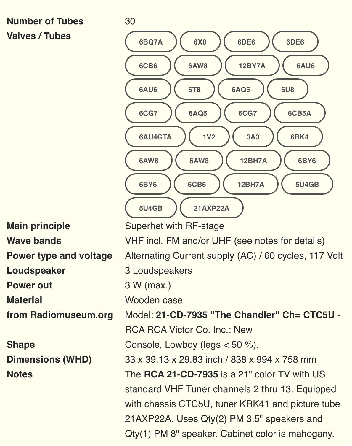
RCA CTC-5 Deluxe Color Television

Courtesy Ed Reitan Estate

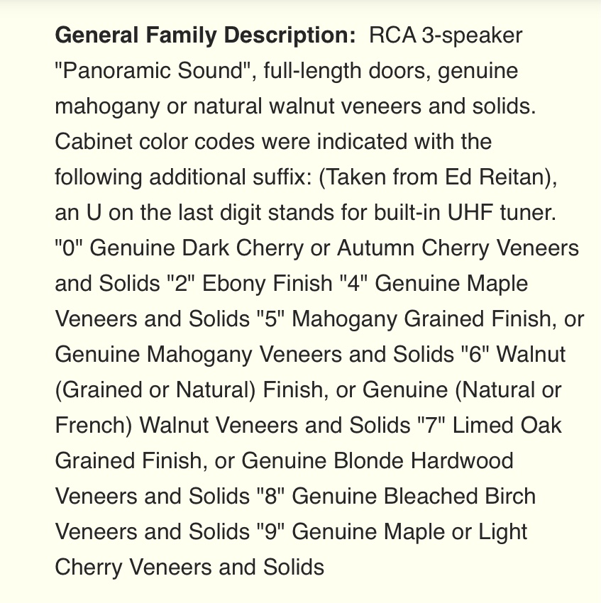
Courtesy Radio Museum

Courtesy Radio Museum
Late Saturday night, January 6, 2024, our friend from the city of lights suggested we check out a Craig’s listing. It was an RCA CTC-5 in great shape, needed work with a good 21AXP22A and it was close by in Tucson, AZ. We jumped on it, messaged the seller and the next morning, he called. Within the hour we were on our way, making the 158 mile trek in just under 3 hours. Weather wise it was a miserable day, chilly and raining but we didn’t let that deter us. The seller was Bruce (hi_volt) known to me from interactions on the VideoKarma forums. Bruce purchased the set from a gentleman in California and never attempted to restore the set where it sat as a static display in his den for years.
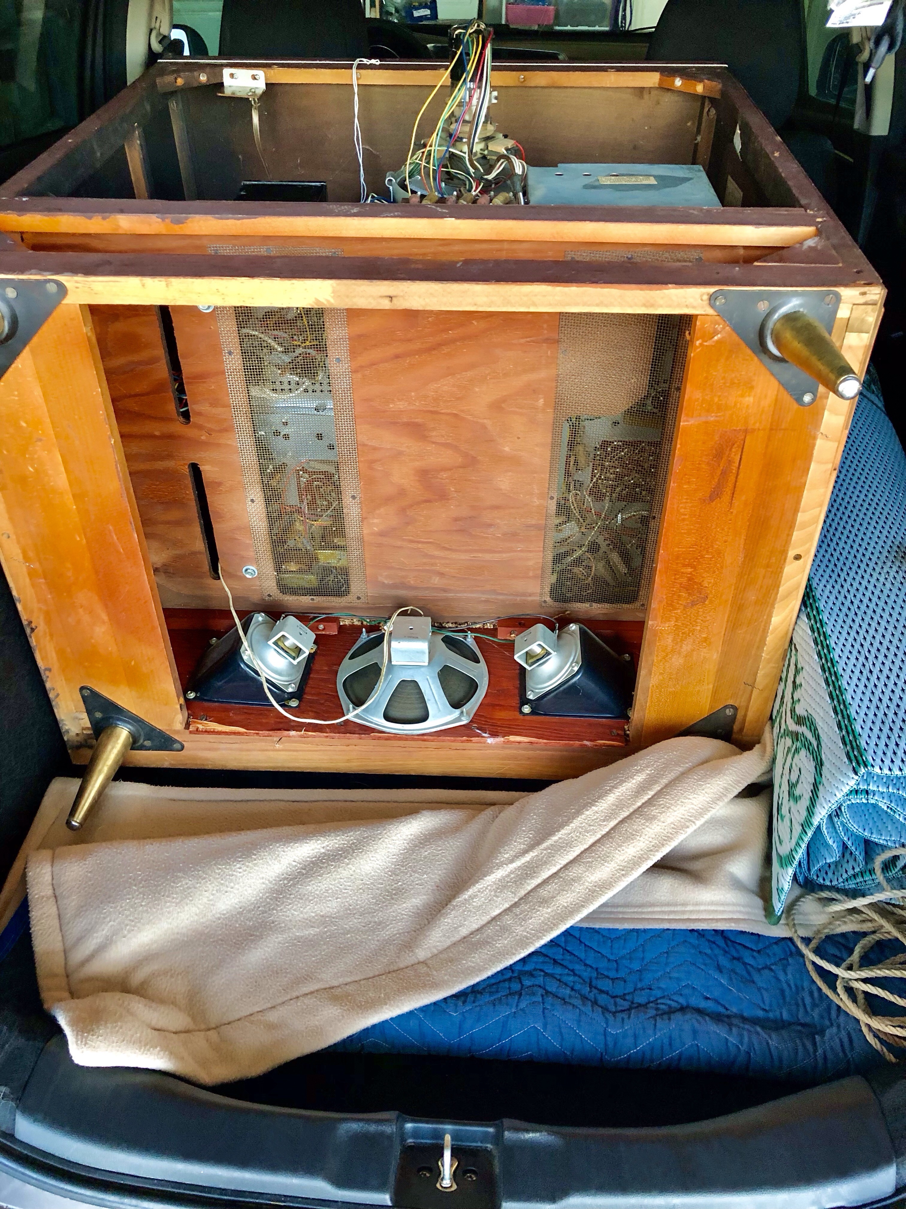
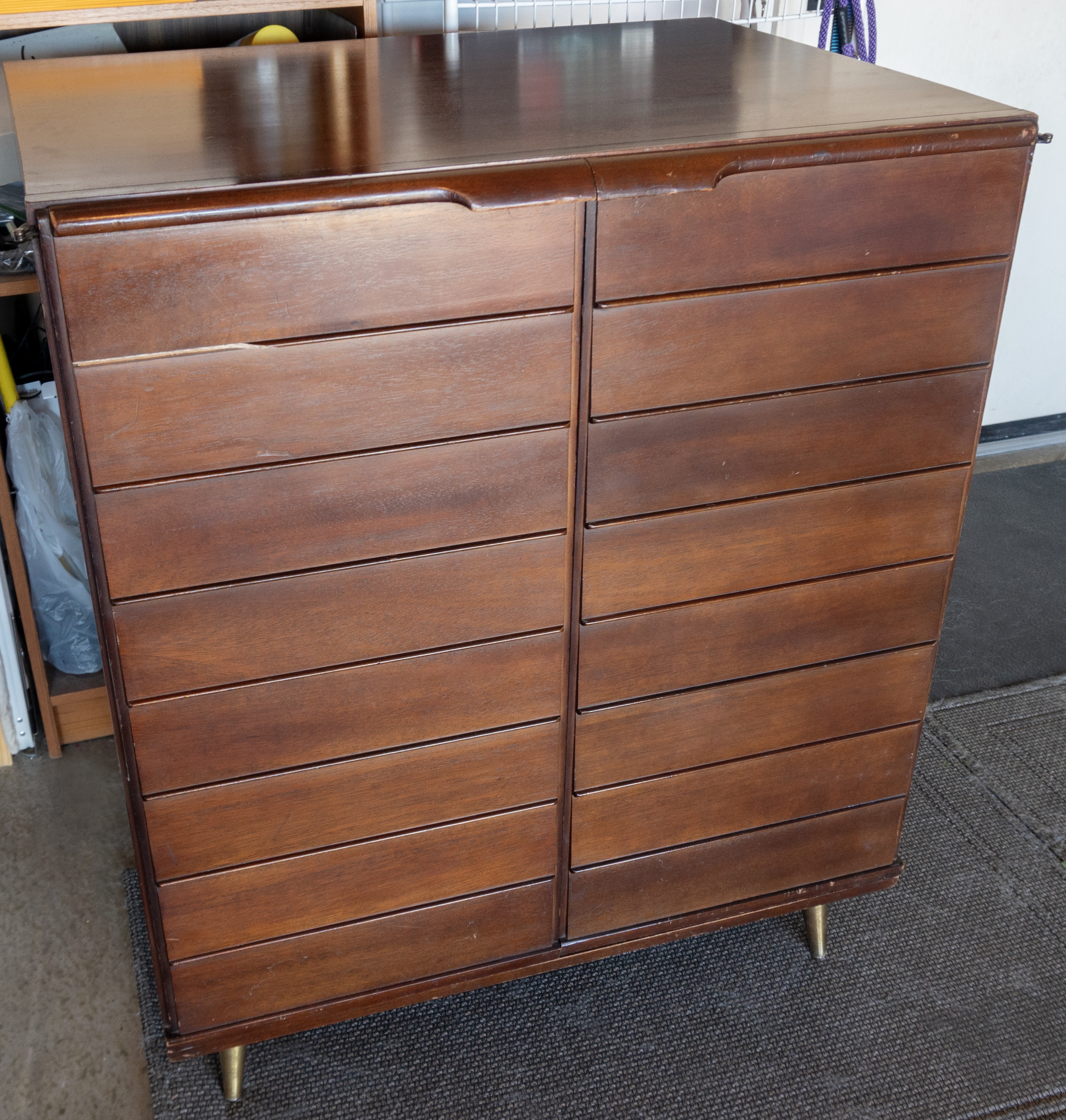
We wrestled the CTC-5 into our Honda and headed back to the Phoenix valley. Here a photo of the set in the car in our garage.

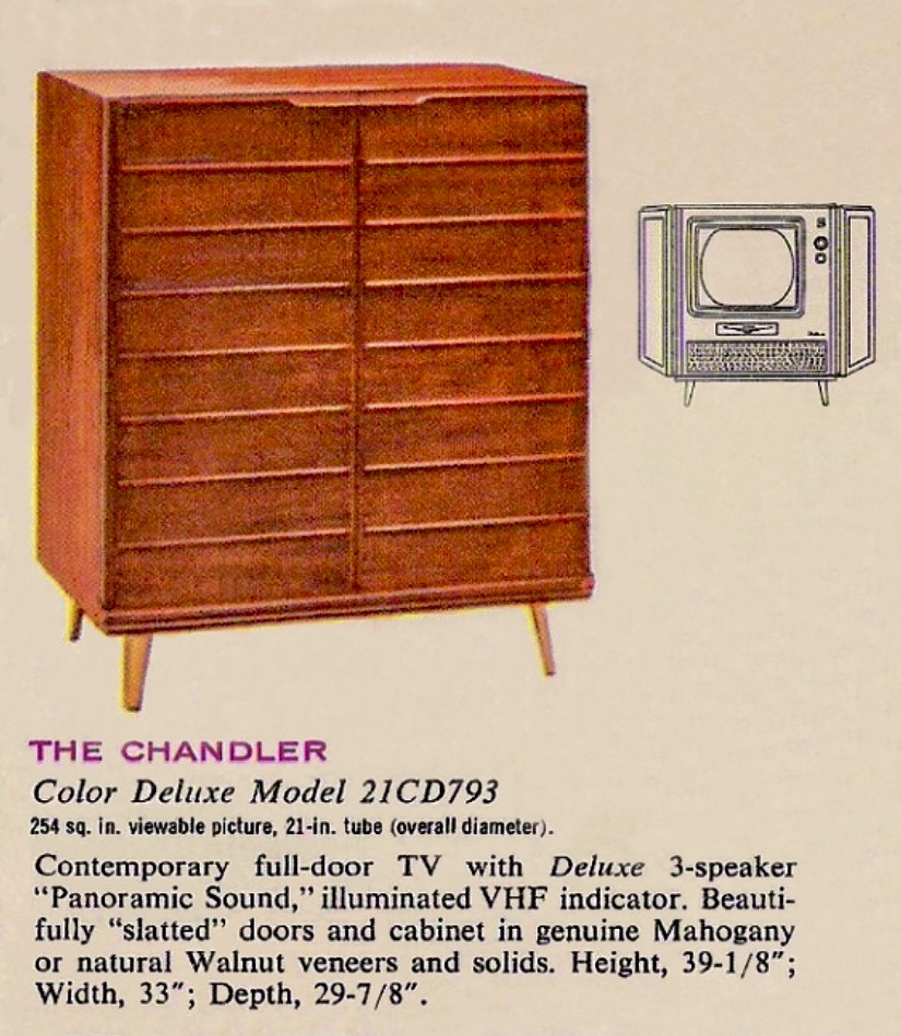
A view of the 3 speaker “Panoramic” sound system.
The next day my neighbor and I pulled the heavy beast out of the car and here it sits in our garage.


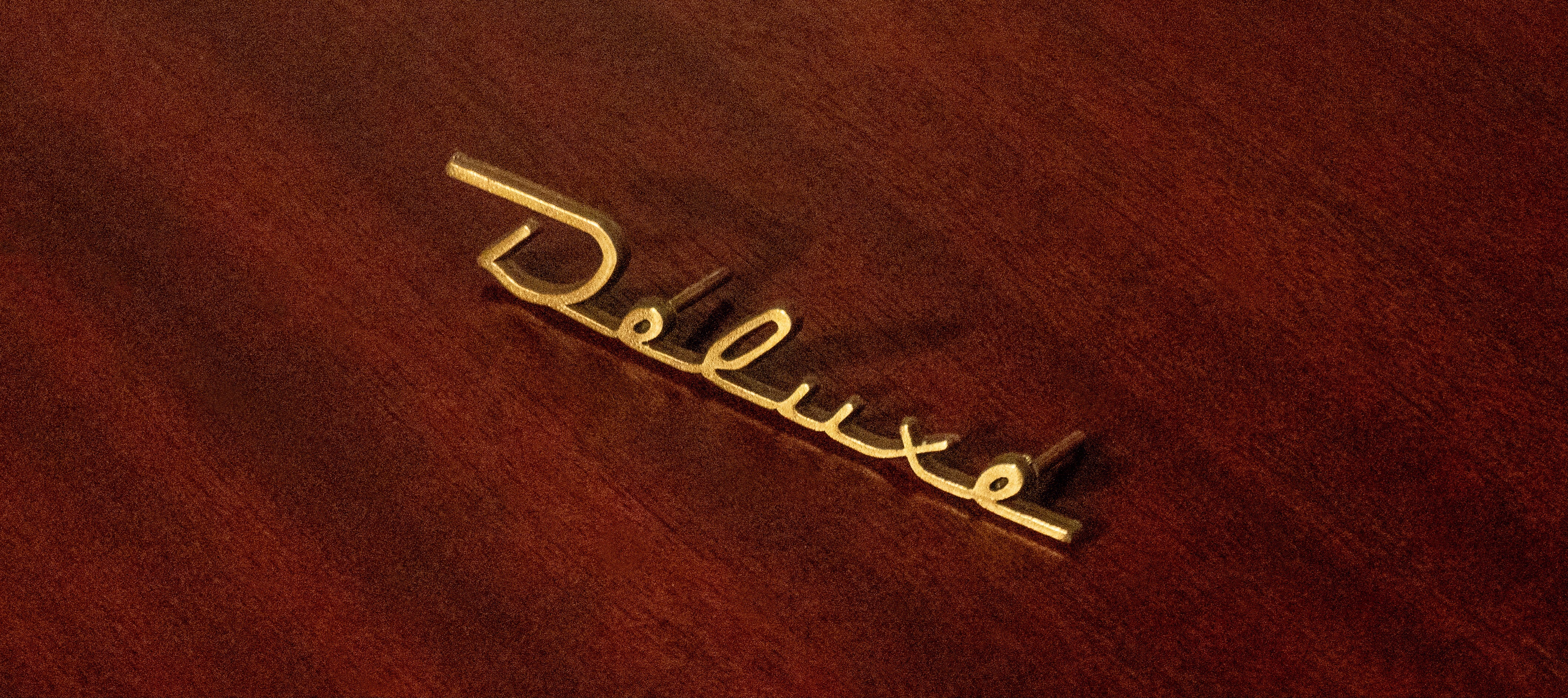
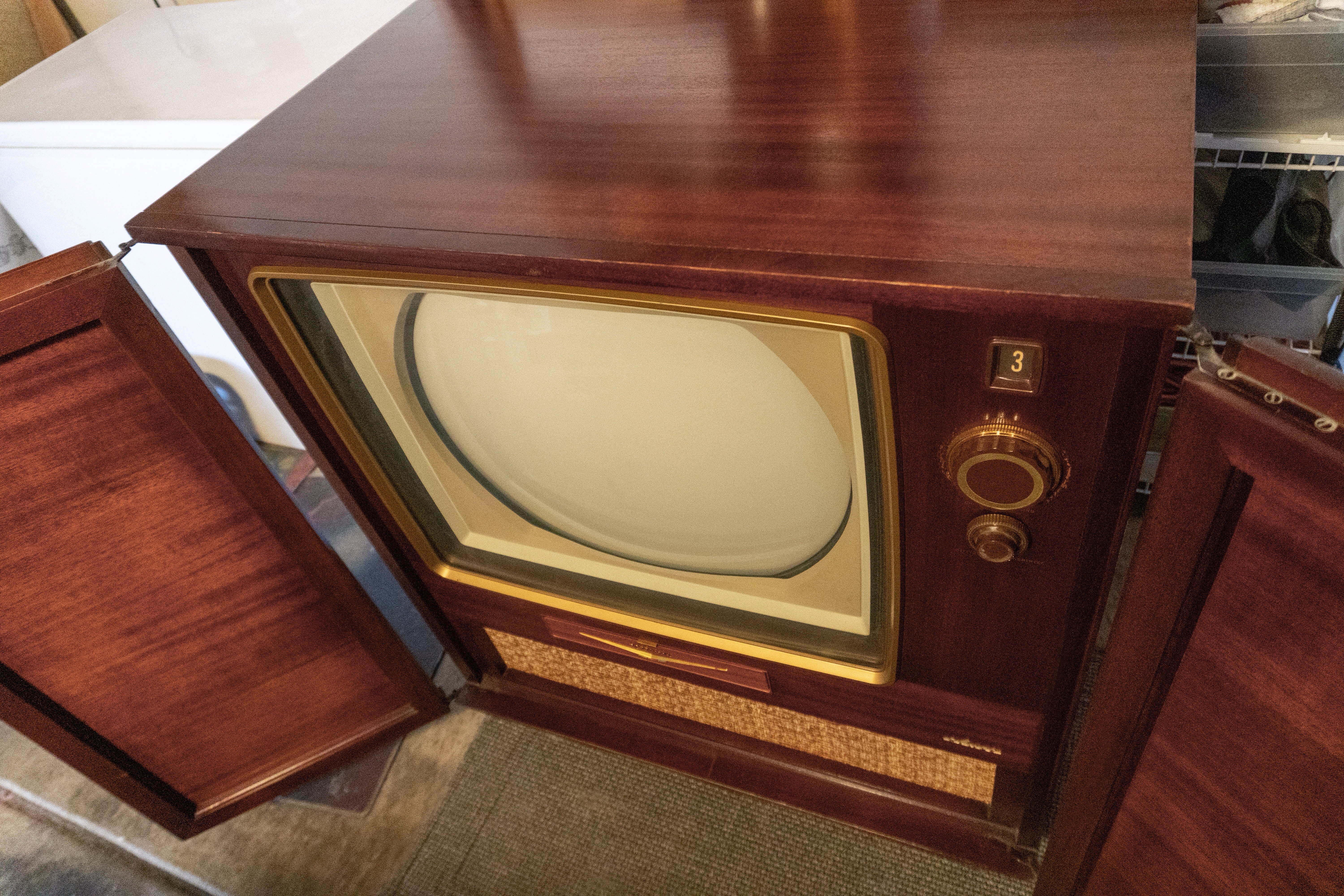
The Deluxe badge with the “D” missing. This happens when a polishing cloth gets hung up behind the badge. We have a replacement reproduction badge


Beautiful fluted doors.


The cabinet is in remarkable original shape and only requires minor touch up with mahogany wood paste. The above photo with fingernail damage around the channel selector is the worst of it.
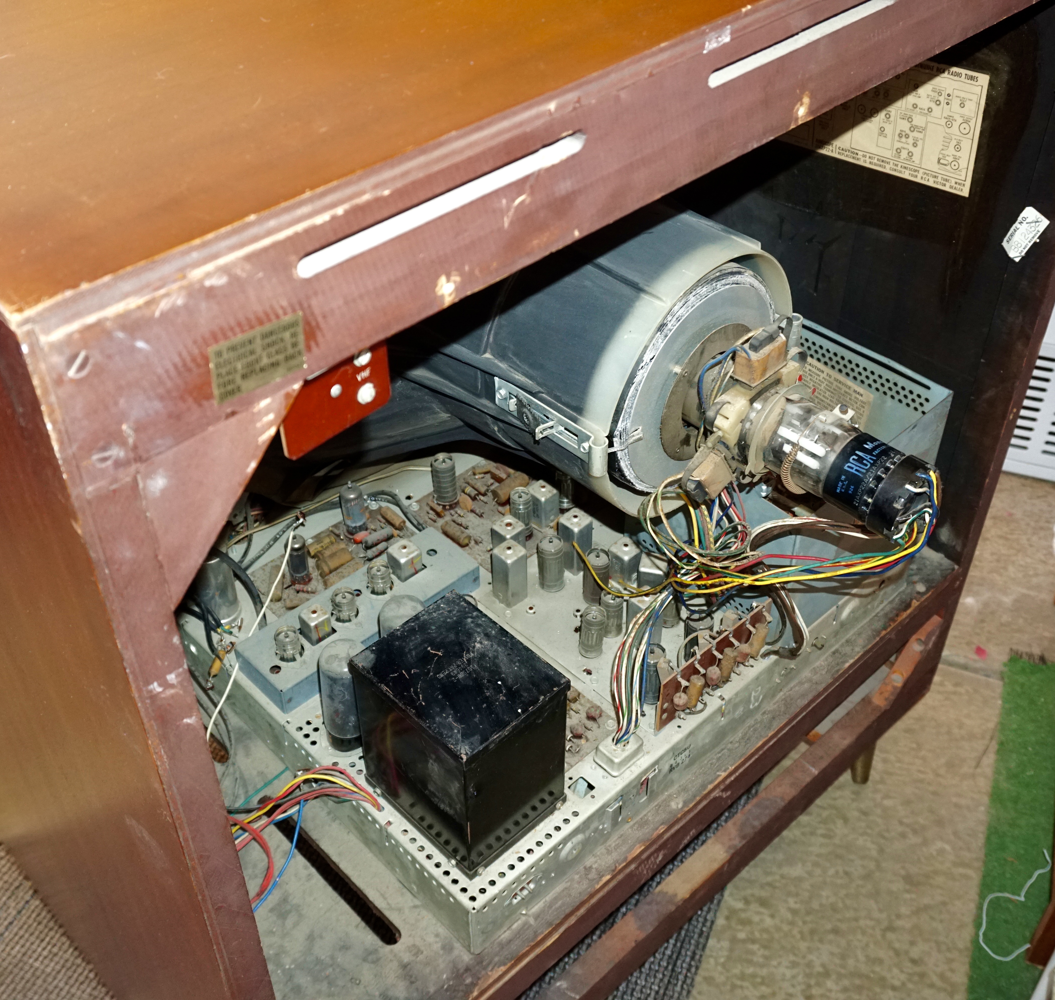
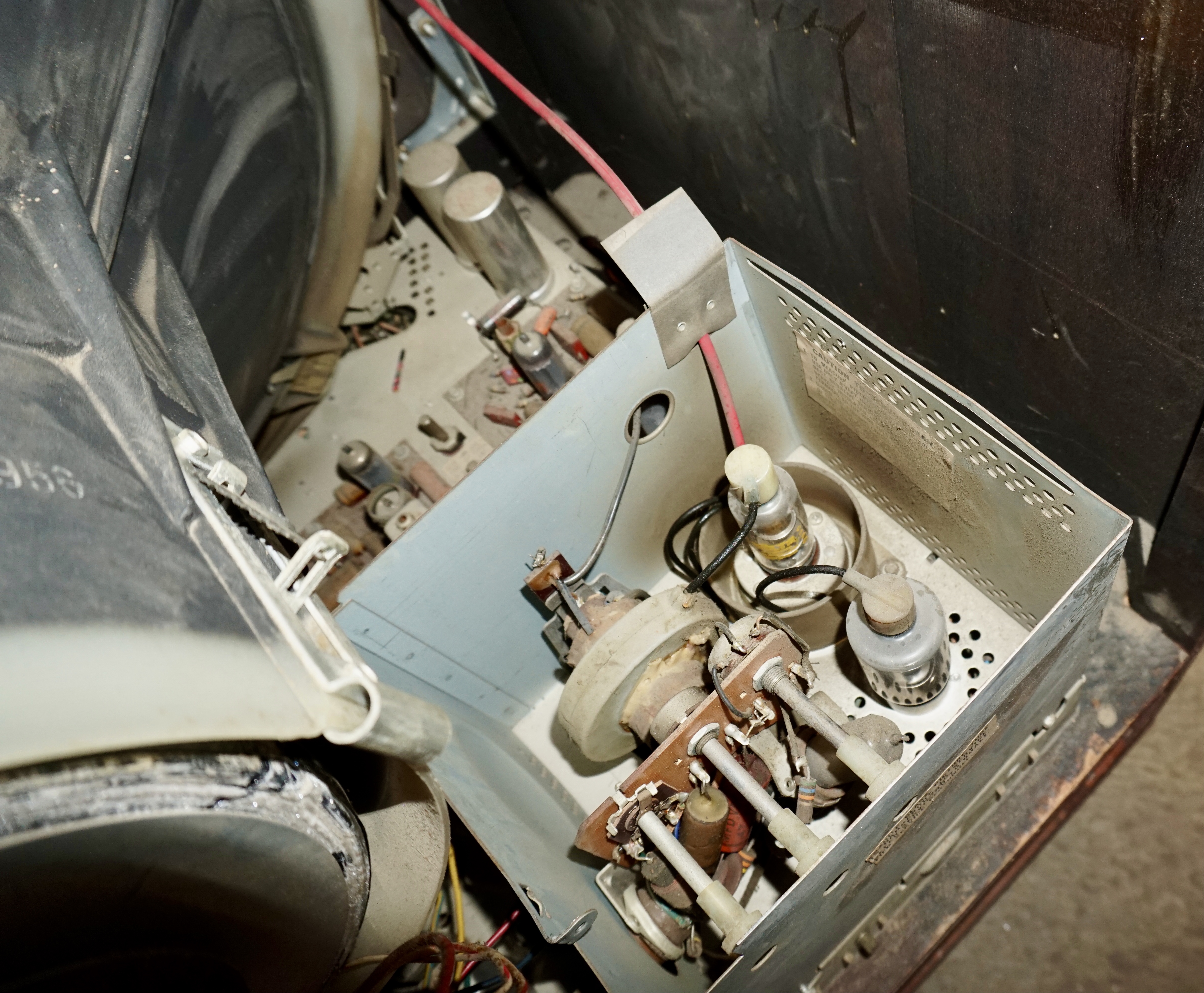
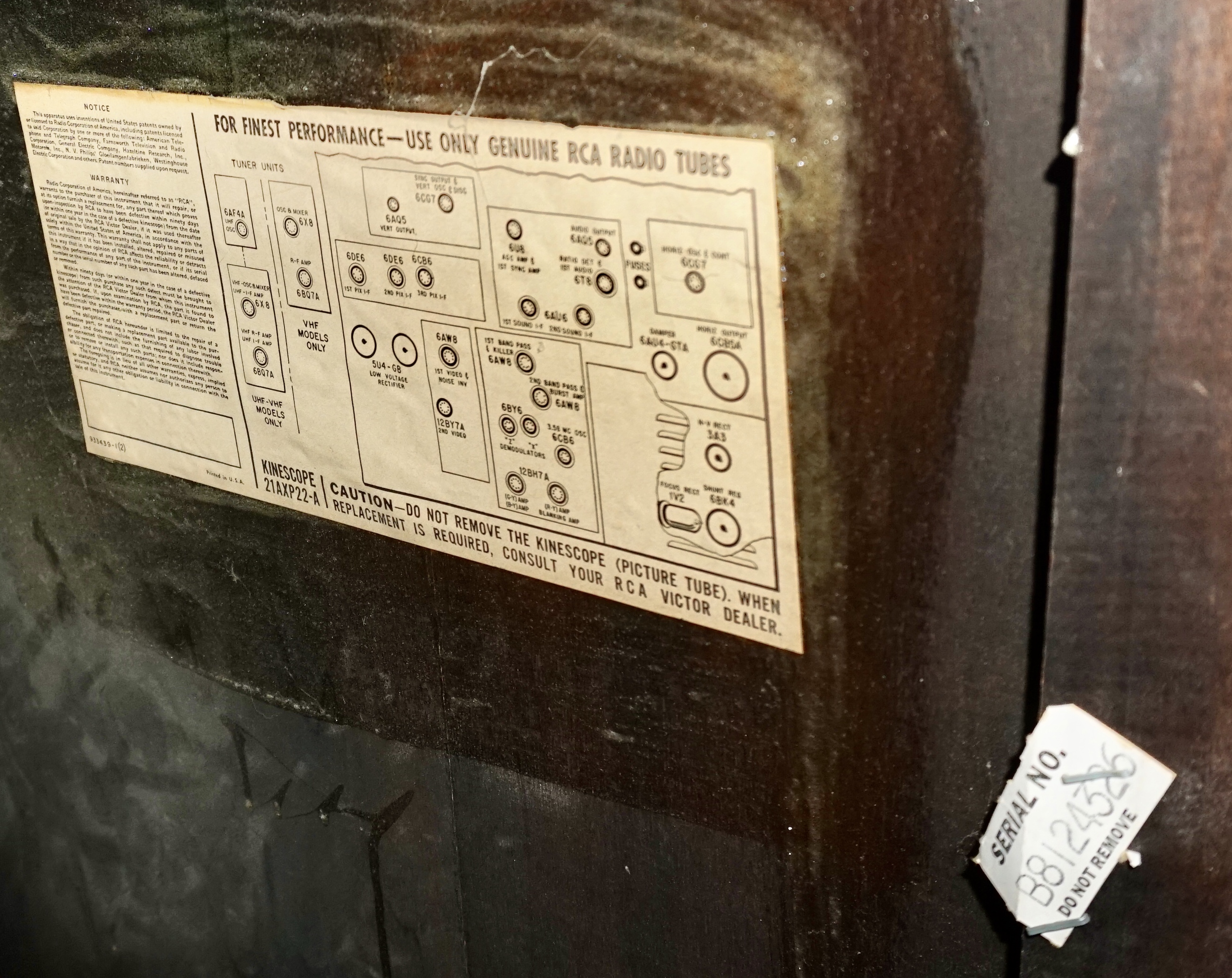
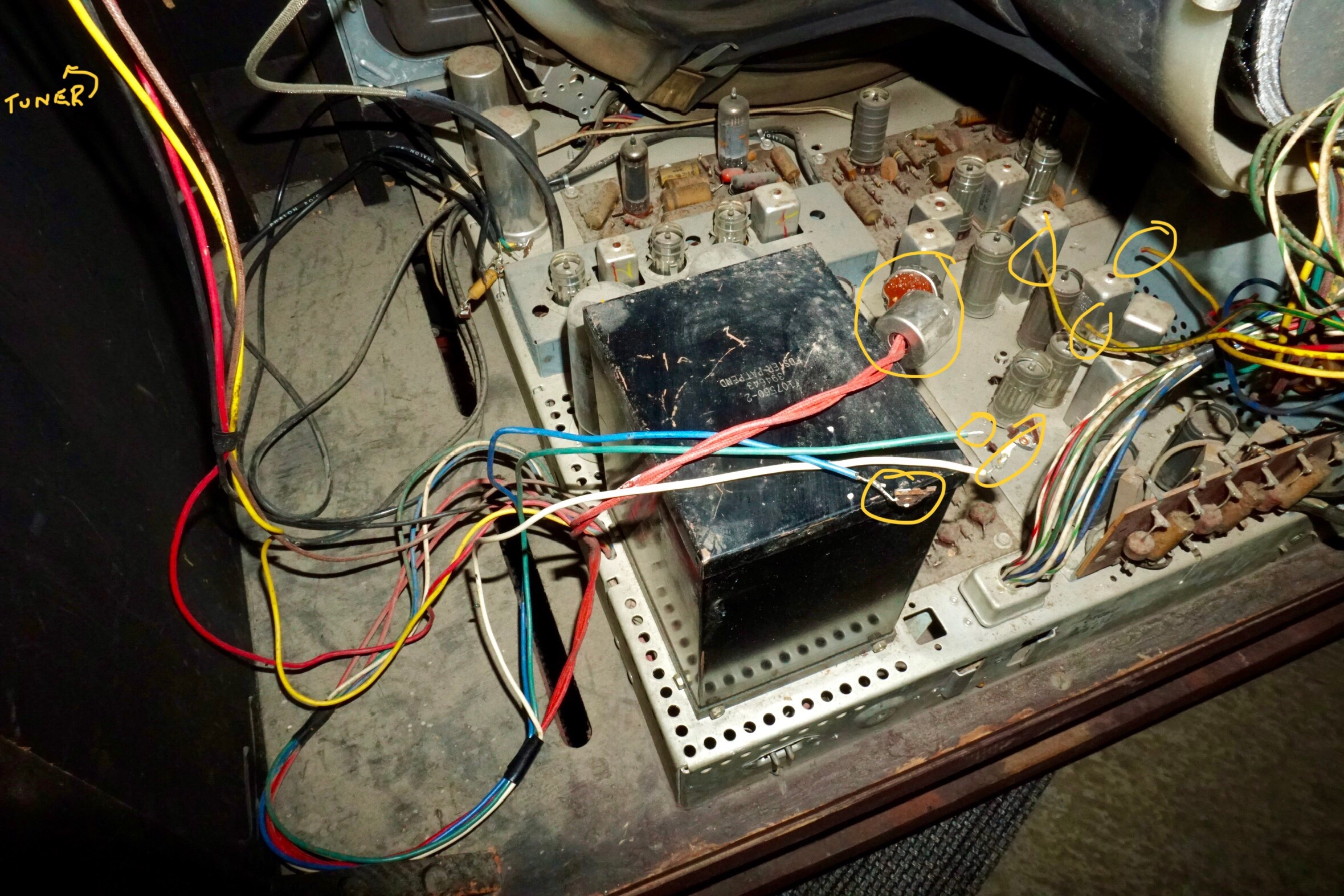
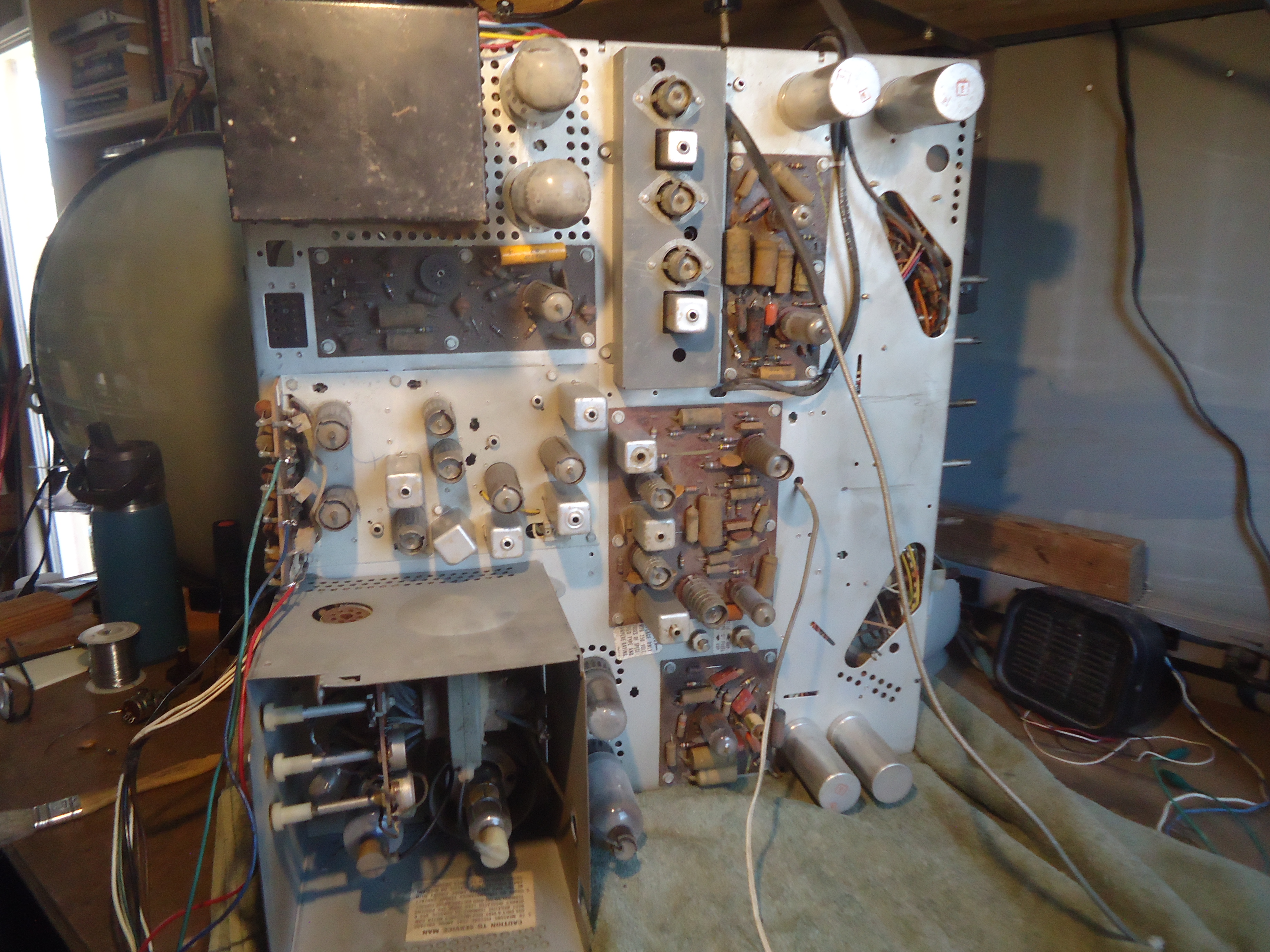
Views of the original chassis, 21AXP22A and flyback with decades of dust. Going in, the 12BY7 tube is missing, also the rear panel and high voltage cage cover are missing. Some wires from the CRT are cut and a concentric control is damaged. That 3A3 looks hot. A date code, September 27, 1956 appears on the CRT shroud. The CRT tested good on all three guns. Serial numbers can be seen in the photos below. According to Ed Reitan’s website, the Deluxe chassis uses superior X and Z wide band color demodulation.


Cut wires from volume/brightness control and three wires from CRT socket.
We plan a full complete restoration.
January 13, 2024
I’ve added two articles from RCA Review courtesy American Radio History regarding the development of the 21AXP22. First article starts on page 122 through 169.

Click to access RCA-Review-1955-Mar.pdf
Second article starts on page 143.
Click to access RCA-Review-1956-June.pdf

Click on image to open, courtesy Franks data sheets.
RCA Service Clinic Courtesy Early Television Foundation.

Click on image to open PDF. (Thanks JH)

Courtesy Ed Reitan estate


Courtesy Life Magazine October 22,1956
Update, December 24, 2024.
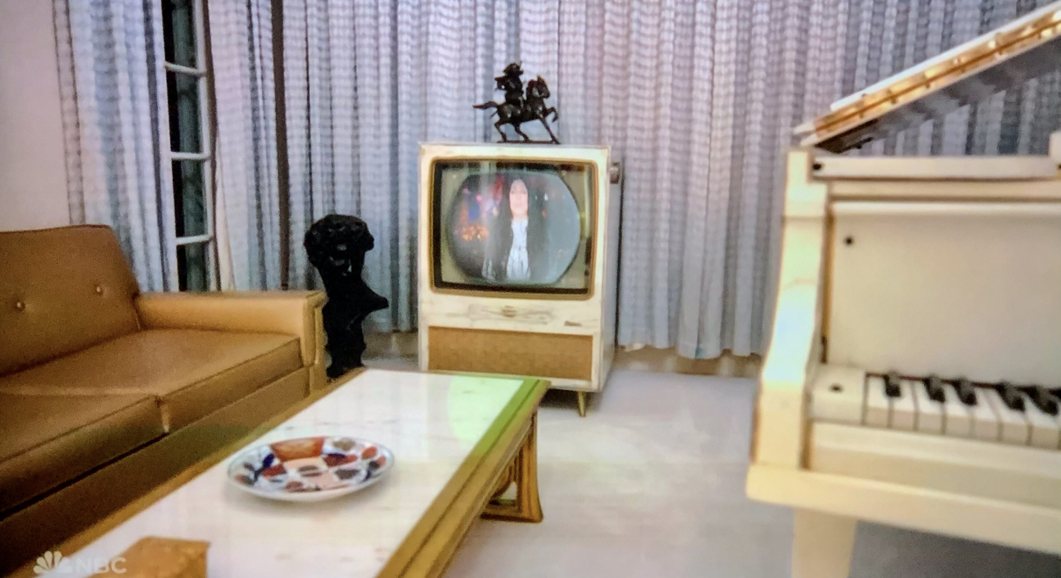
Elvis owned a CTC-5.
This screenshot image was captured from my OLED LG television on December 24, 2024 of a scene from the NBC special, “Christmas at Graceland”. The image is the iconic Elvis Presley piano room which appears to show an RCA Westcott CTC-5 color television. This room photo has appeared many times in the past and what is unusual, Cher is narrating this scene while on the Westcott screen, appears a live video of Cher narrating. As we watch, the camera closes in and the scene dissolves to a full screen HD image of the same video image of Cher.

May 6, 2024, day one.
Restoration begins.
Mike Doyle came by today to pick up the CTC-5 chassis and take it to his shop. He will jig the chassis to a test color CRT. He needs to finish a Korean prewar radio and after, will restore his own personal CTC-5. After that he will start on my CTC-5, the subject of this post. Mike has restored two other CTC-5’s prior to this project and is familiar with the circuit design and layout.
Below, a few pictures of the disassembly.
Photo #1 RCA added printed circuits with this model and looks to be original.
Photo #4 6X8 tube missing from tuner assembly.
Photo #6 RCA Monogram factory rebuilt 21AXP22, serial # CC11949.
Photo #7 Emissions test of CTC5U chassis.
Photo #8 All three guns test very good.
Photo #9 Life test reduces filament voltage by 10% and no change in very good to excellent readings.


May 24, 2024
Today, we moved the CTC-5 cabinet and CRT into our home theater room, awaiting the restored chassis from Mike. I do not plan on restoring the cabinet. It’s in remarkable condition with only a few nicks and fingernail damage around the channel selector.

July 25, 2024 Day 81
It’s on the bench.
Mike was finishing up on two prior projects and so the “official” start of restoration begins today.
From Mike,
It is on the bench. I will be connecting crt wires back to where they need to be and I will install the volume/on/off brightness control with a new switch unit. I will install missing tubes and fire it up to see “what we have got” for the beginning of restoration.
Here we gooooooo!!!
Mike
July 28, 2024 Day 84
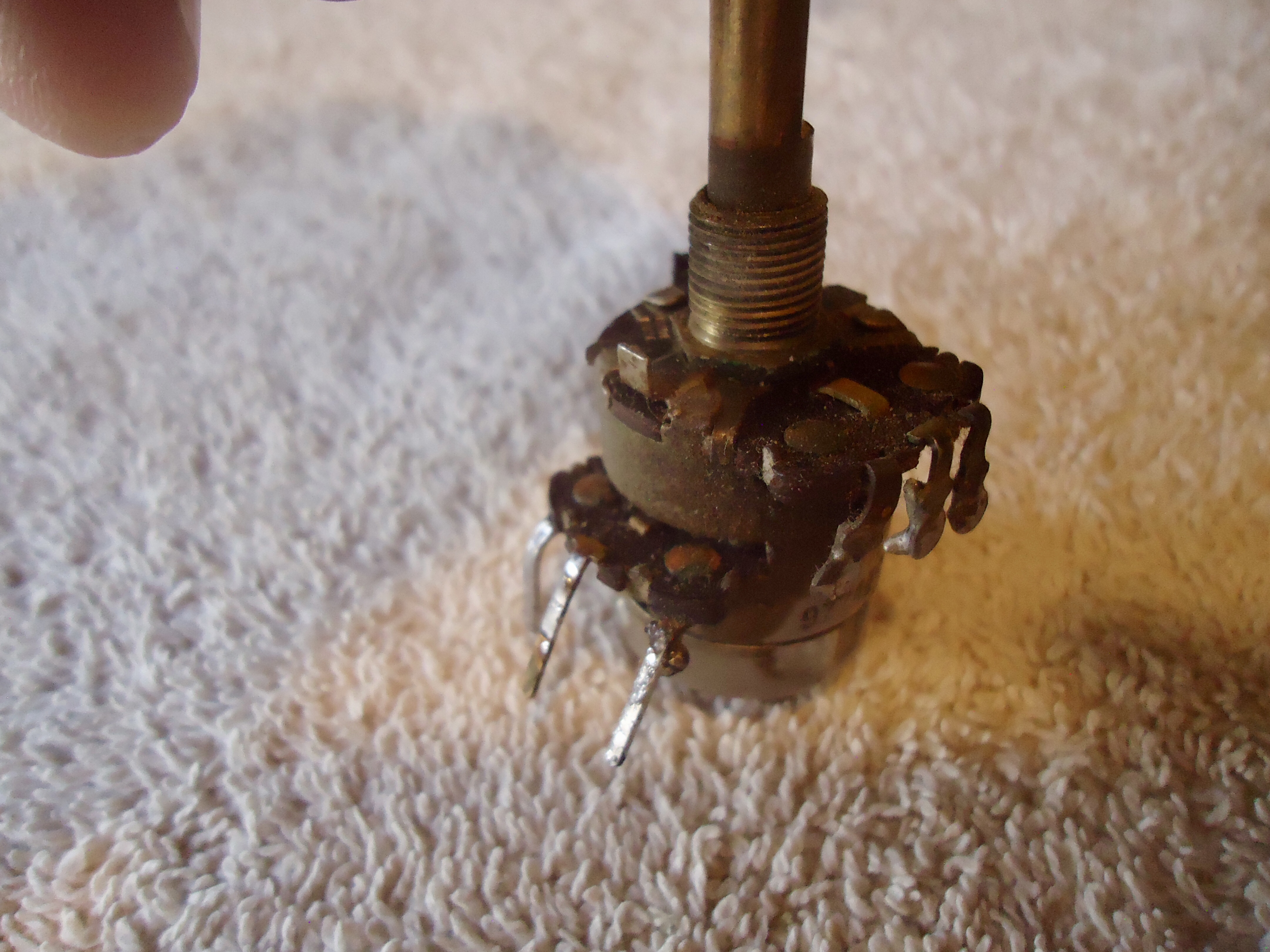
Volume/Brightness control rebuild
From Mike,
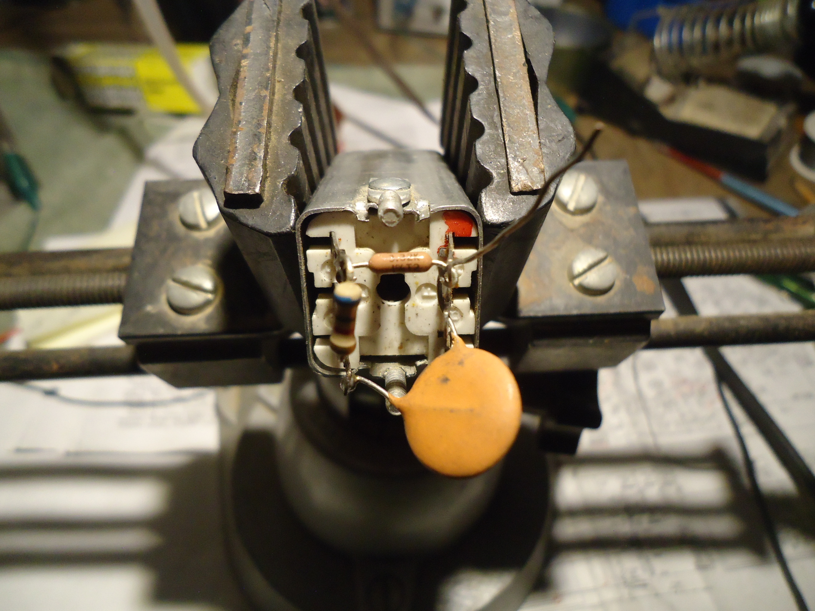
The chassis came to me with no brightness/volume/switch control. That part was a bunch of broken pieces. I had a control assembly in my parts pile, but in checking it out, the switch was bad and the 1 megohm volume control pot was “open circuit” The part number for this piece is RCA 102156 which, as far as I can tell is un-obtainable. If this chassis is going to work again, the control that I have here would need to be re-built. A very delicate operation. The problem was the brass rivets that contact the wire lugs to the carbon path of the pot were loose. So, I had to try something that I have never tried before, and apparently, it worked.
Pix 1 Volume/Brightness/switch loose wires and damaged parts from the original assembly.
Pix. 2,3,4 My control with issues like open 1 meg volume control and bad switch.
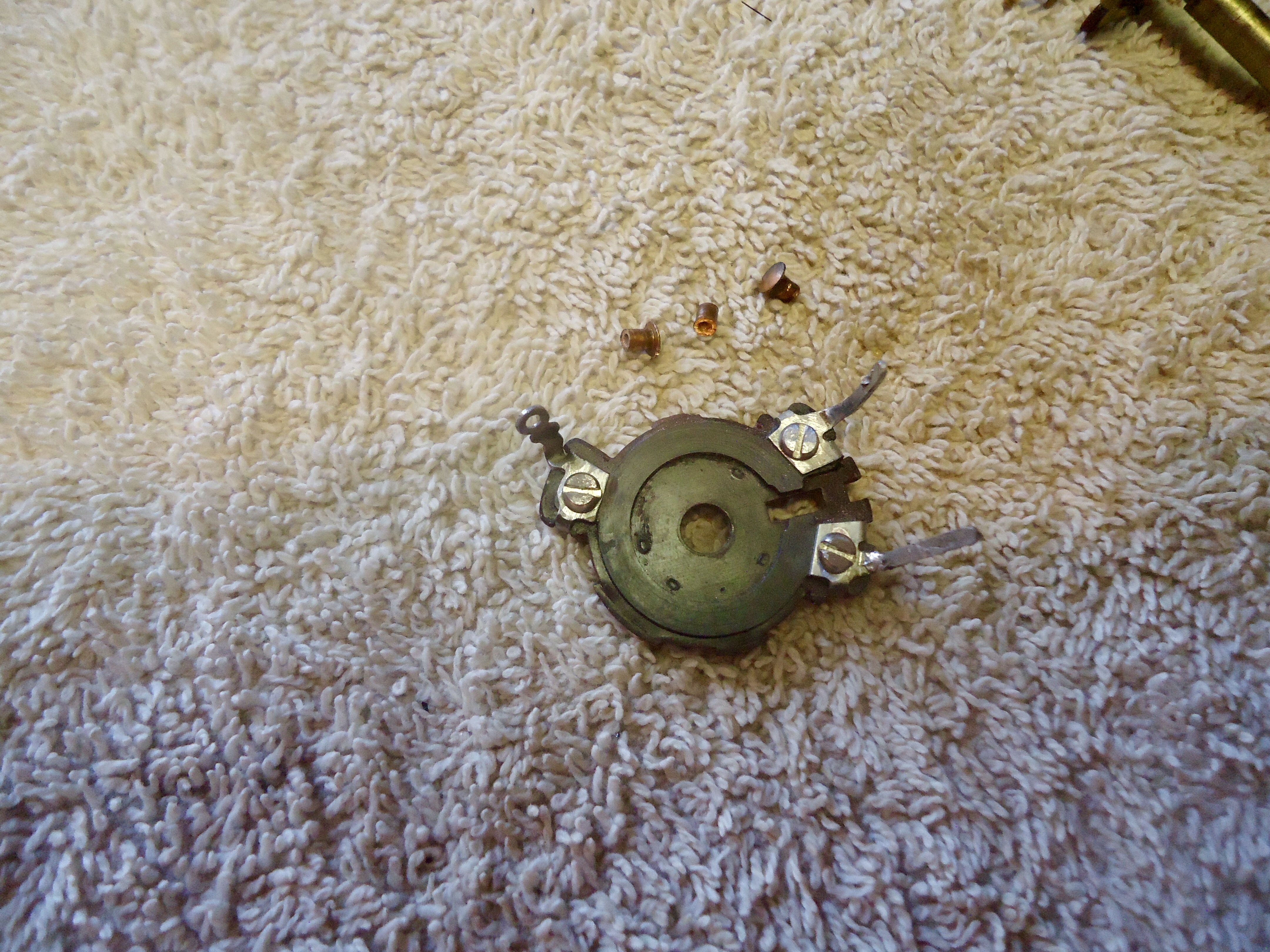
Pix. 5 Pieces retrieved from broken assembly. These had some usable parts that I used in the re-build process.
Pix. 6 Disassembled for repair.
Pix 7. I started by drilling with a pin vise by hand to remove the brass rivets, but the rivet started rotating so I switched the tooling to Dremel tools. This worked well.
Pix. 8. The repair is a success showing the 1 Meg reading on the ohm meter.
Pix. 9,10. Details of the #2/56 screws that replaced the rivets that I removed.
Pix. 11. Control re-assembled and ready to install including the new switch unit.
Next, is to install this unit and then figure out the connections for the crt wires and get them hooked up. Then, it is time to fire it up and see what we have got.
Cheers, Mike
July 29, 2024 Day 85
From Mike.
Next
The crt wires have been reconnected to the proper points. No tubes have been tested and several of the tubes are missing. I will install missing tubes tomorrow and hook up to the jig. It is time to “see what we have got” before any further restoration procedures. The next 4 pictures are as follows.
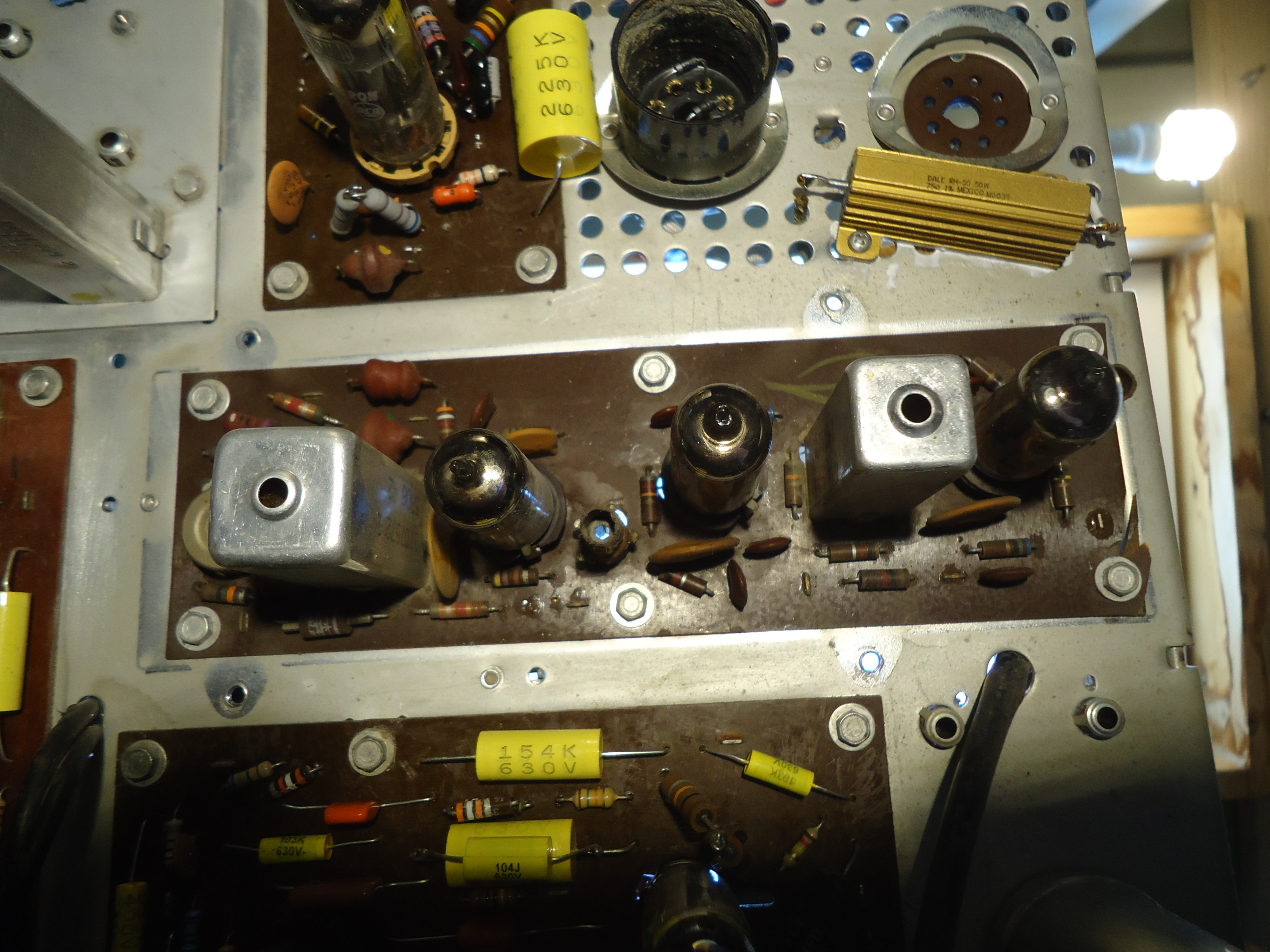
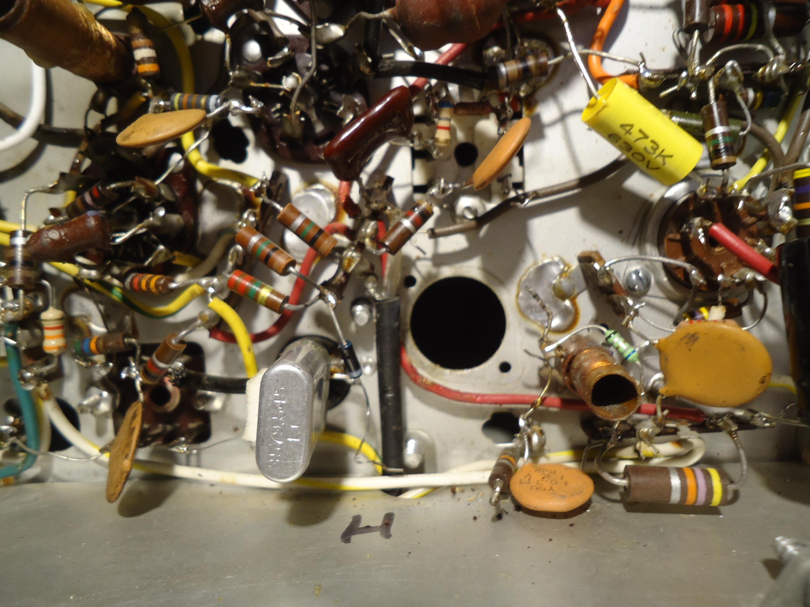
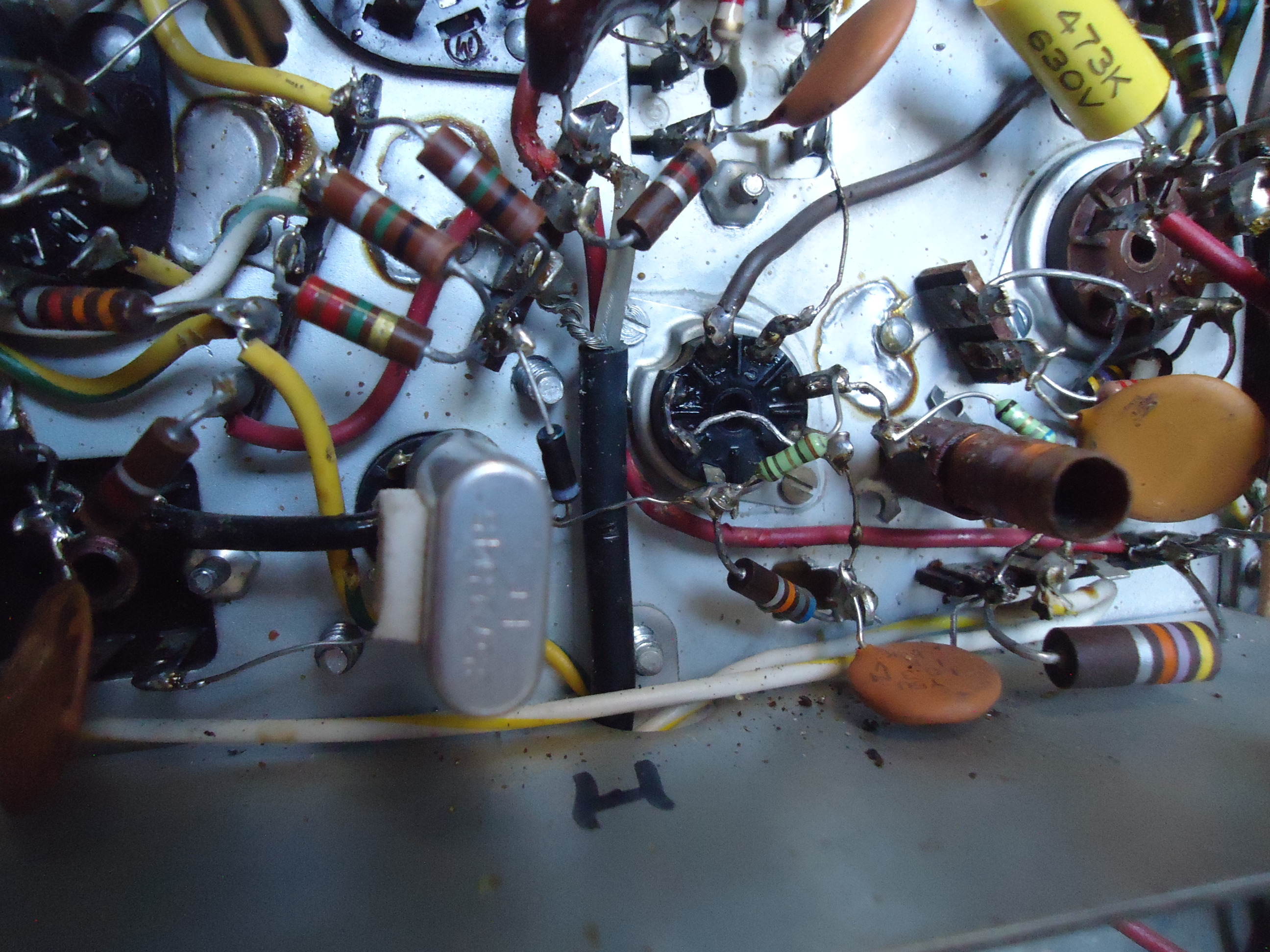
Pix 1 Chassis top view before preliminary cleaning with vacuum and brush.
Pix 2 Chassis after vacuum and brush cleaning. More cleaning will take place as the restoration continues.
Pix. 3 and 4. The newly rebuilt control mounted and wired.
More to follow.
Mike
July 30, 2024 Day 86
From Mike:
Approx 7-29-24.
I jigged the chassis to my 21FBP22 today, connected to a variac for first power up. When I got to full voltage, nothing was alive in the power supply. The D.C. voltages should be 385v,,,, 275v… and 140v. (roughly). All filaments were lit to normal brightness except for the 5U4 Recifier tubes, which were both blown. NO continuity through the filaments. This usually means that they died from an overload somewhere in the power supplies. I checked for shorts to ground, but nothing obvious. I then checked the fuse in the 385 volt line only to find that it was OK. BUT, somebody thought that it was an OK thing to install a 3.5 amp fuse into a place where it there should be a 2 amp fuse. Some technicians seem to think that it is an intelligent thing to do that.
Upon replacing the two 5U4 tubes from my “good used” pile, and replacing the fuse with the proper value, I tried again only this time I monitored the D.C. amps inline with the fuse upon power up. It got to just under 2 amps when the fuse blew. The D.C. 385 volt supply never got over 50 volts with the variac at about 75% which would be around 80 VAC line volts. Still no obvious shorts using an ohm meter, which means that the short is only there with voltage applied.
It is time to start changing all the electrolytic capacitors in all sections of the power supply. There are 4 “cans” on the chassis, and all of them are in the front where the crt insulator boot can interfere with the 2 in the front, if the cans are too tall. I learned this one the hard way a number of years ago when I restored my set. The best way to fix this problem for maximum reliability is to re-locate the caps with individual units under the chassis, and leave the cans in place for cosmetic purposes. Fortunately, there is a lot of room to work with under the chassis to accomplish this task. I cut out the studs on the cans one at a time for further clues with the ohm meter. What I found was that several of them were leaking voltages from section to section, rather than the normal failure mode of stud to ground. This did offer some explanation to the overcurrent condition with voltage applied. I spent a lot of time over the next few days mounting tie points for the new capacitors.
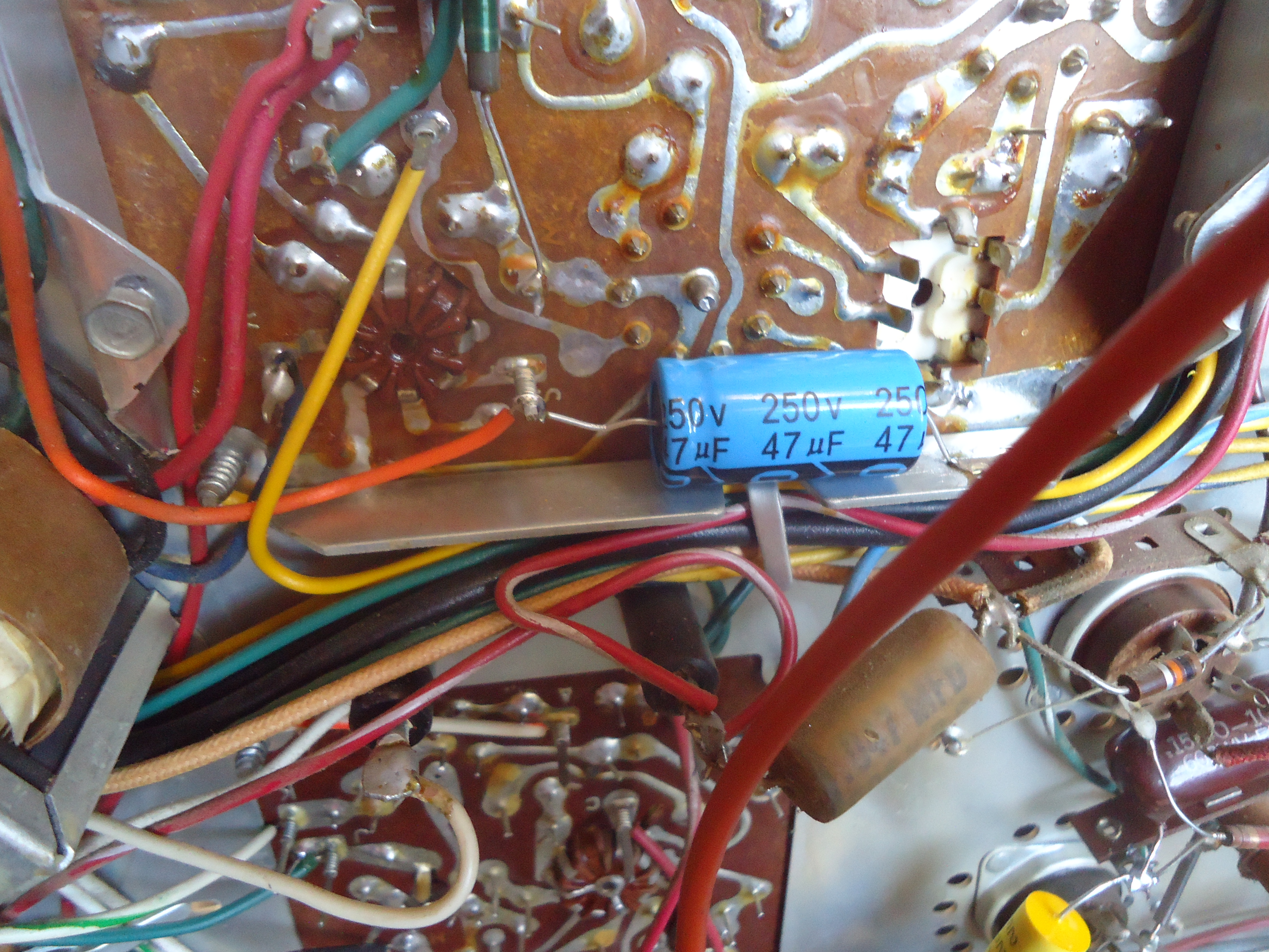
Pictures 1 through 4 are the newly mounted electrolytic capacitors and some others that I replaced since I was already working there where the new ones were mounted.
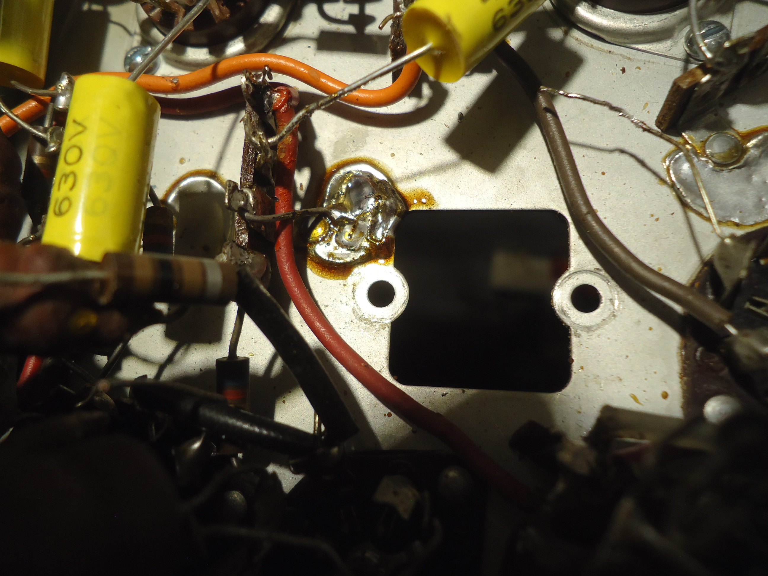
Upon the next power up, I had 325 volts of D.C. on the main output of the rectifiers. Some success! It will likely be much more like 385 later when I install NEW 5u4 rectifiers, but this voltage is fine for now during more troubleshooting. I now have weak audio but NO high voltage at all. A quick check of the Horizontal output and damper tube showed that they are probably OK. So, a quick check for a Horizontal Oscillator drive signal on the control grid of the output tube showed NO signal there. The oscillator tube checks ok but I tried a new one anyway. No change. I then checked for B+ at the osc. stage and that looked OK. Then I got lucky when I did a careful physical exam on the osc. board. I was prompted to do this since I noticed that some tech ahead of me mounted new capacitors on top of the board. That is not a good thing to do because it often times weakens the solder connection on the bottom side. That is when I found the capacitor that is across the oscillator coil had a cold solder joint. These oscillators work much better when the coil and capacitor are actually connected to the circuit. (sarcasm) .
Picture 5 The red pen shows the point of cold solder joint.
Picture 6 The previous techs “handy work” on top of the board. (sarcasm)
Picture 7 Signal now present at the grid of the H. Output tube.
But, still no high voltage even after I changed the 3A3 HV rectifier and the 6BK4 Regulator. Further troubleshooting continues.
Cheers, Mike


August 7, 2024, Day 94
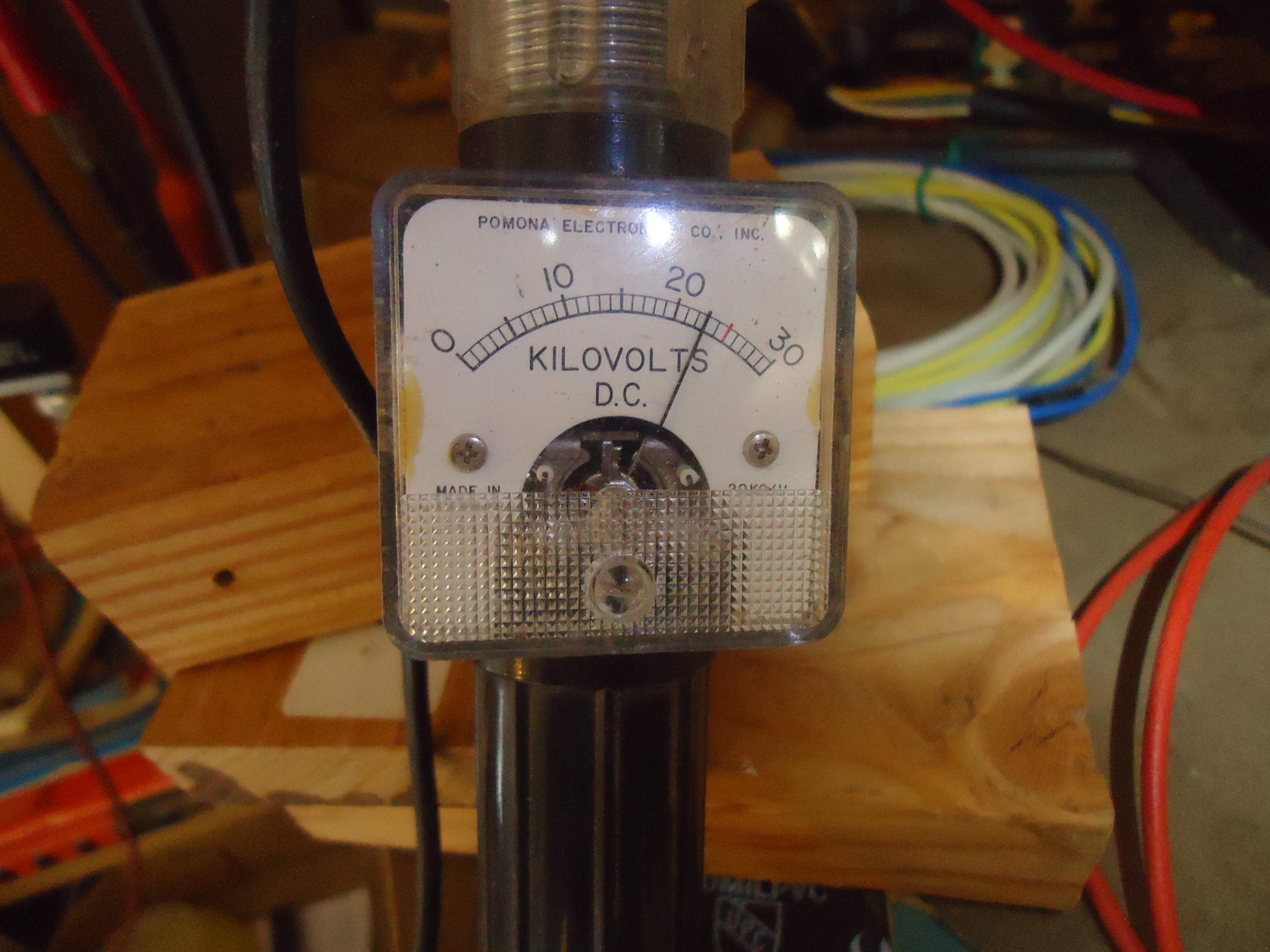
OK, I really do have High Voltage! My H.V. meter that has been very reliable for over 40 years lied to me! As I moved the schematic to a different part of the bench, I noticed the hair on my arm standing up when close to the CRT face. I swapped out the H.V. probe and it measured 16 KV. So, that is not enough, but good for now!!
Pix 1 First image on this set for likely many years shows no sync, or maybe AGC issues. Hard to say. But I am going after the Horizontal Osc. board next.
Pix 2 Parts removed. I replaced every part on this board except for the coil, which is obviously OK. All caps are new. Some resistors looked tired so they got replaced good or bad.
Pix 3 Rebuilt Horizontal Osc. board.
Pix 4. First good image with color. I still suspect maybe there is an AGC intermittent, but this is a milestone in the restoration process since it tells me a lot about the rest of the set.
There is still a lot of work to be done. I installed 2 brand new 5U4 tubes and the power supply voltages are now what they should be. I have tested all of the tubes and found several weak ones and they have been replaced. There are a number of controls that have issues and I am not sure if cleaning them will help. Most of them have to do with convergence. I may be facing some rebuilding of controls like I did with the volume/brightness/switch unit. Time will tell. Next, I plan on going after the Sync/AGC/Sound I.F. section. Even though the High Voltage is low, I am not too concerned with that for now. It should be 22KV.
Onward, Mike
September 20, 2024, Day 138
From Mike. I am slowly changing parts on the Sound, AGC, Sync printed board. I have found a number of questionable solder connections along the way on this board. It has forced me to change every single component except for the transformers which are typically not problematic. Somebody missed “solder skills day” in the process of manufacturing. I think this set was very problematic from the day it left the factory. Obvious bad solder joints with component pins easily seen moving when exercised from the top of the board. Also, I found some notes in my CTC5 “red line” drawings that reminded me of a mod that I made on my set in the High Voltage Regulator. I added a HV control. I will be doing that mod on this set. It entails removing a control on the back panel that never did anything. It is called the Matrix Balance control. It is supposed to control current in the “X” and “Z” demodulator tubes by way of adjusting cathode current. This is the only RCA color chassis that ever implemented that control and it was eliminated. All sets after CTC5 used a fixed cathode resistor, which is the best way to go. I will replace that control with a 10 Megohm pot and a resistor divider in the HV regulator tube circuit to allow for HV adjustments.
More to come. Cheers, Mike
September 25, 2024
Update for AGC, Sync, Audio rebuild
The printed board that controls AGC, some of the Sync and all of the Audio has been completely rebuilt. I replaced all of the components on this board, not just the capacitors. I found some resistors out of tolerance and a number of cold, poor solder joints throughout. This board was no doubt causing multiple intermittent problems for many years, one of which I experienced earlier in this restoration. There was a horizontal sync problem that mysteriously went away. I decided to do a complete component replacement as opposed to looking for intermittent solder connections and/or faulty components. The CTC5 had numerous issues with AGC and most of that is due to the fact that the engineers thought that it was a good idea to create the 140 VDC power source from the cathode of the audio output tube. VERY BAD design to mix any two circuits that way. I do not know why they did not just add a 20 watt resistor to the existing 285 volt supply which would have been a better design. It would have been a very robust design compared to making the audio output tube do the work of making the 140 volt supply which caused many problems that were difficult to troubleshoot.
Pix 1 Board before restoration.
Pix 2 Board after all components changed.
Next, I go to the High Voltage Regulator and make a mod to allow control of the High Voltage setting.
Cheers, Mike


November 24, 2024
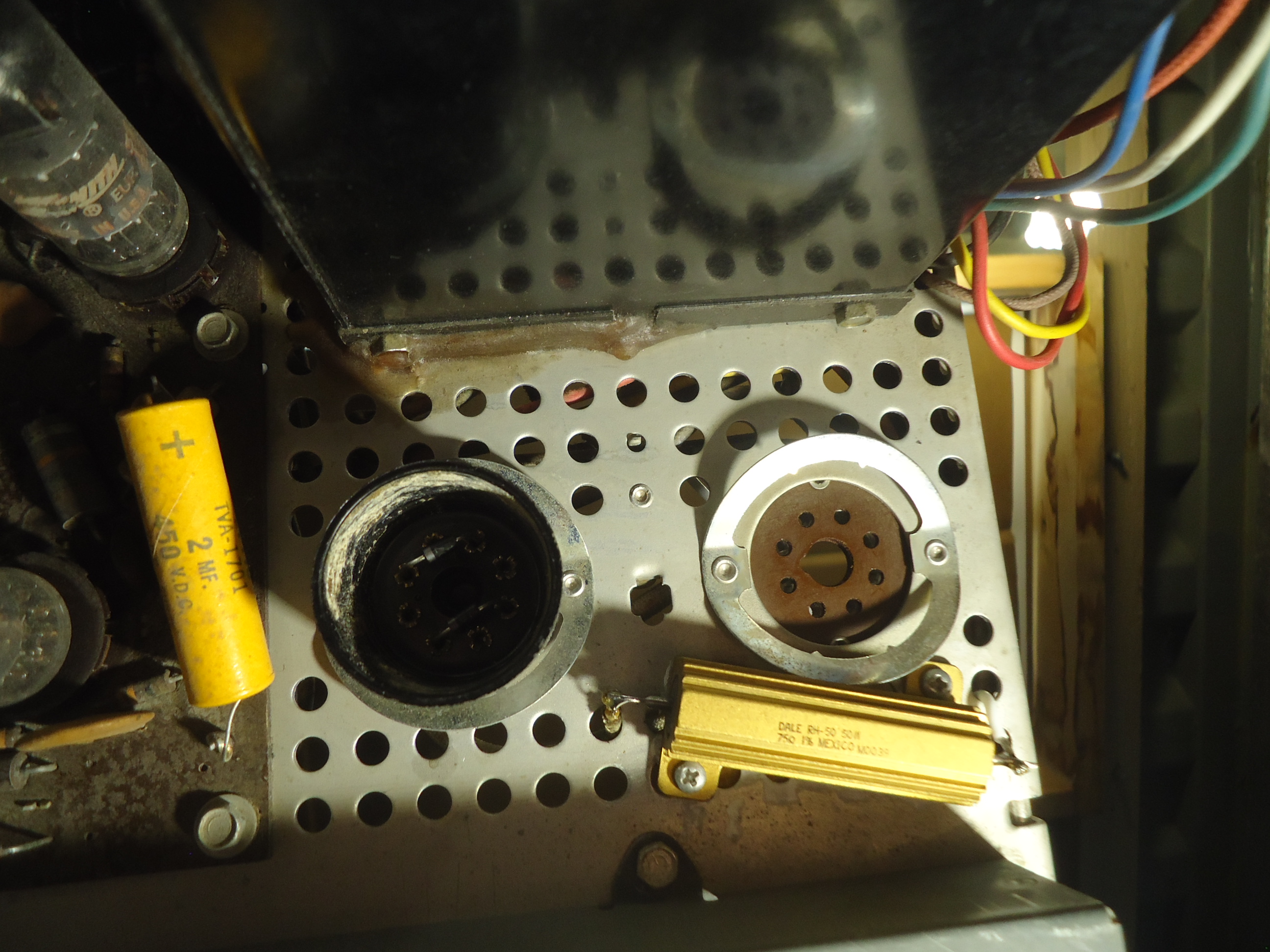
Greetings Marshall. I started looking at the CTC5 again this evening and I will be attacking the H.V. regulation modifications next. The plan is to install a H.V. adjustment control in place of the Matrix Balance control which is located right next to the 6BK4 regulator tube socket. The Matrix Balance control never worked on any CTC5 that I have ever worked on. Every chassis that followed the CTC5 did away with it and replaced it with 470 ohm resistors at the cathodes of the demodulator tubes, and that is what I will do here. The pictures attached are as follows.
Pix 1 The parts that came out of the AGC, SYNC, Audio I.F. board from the last update. I missed sending it at that
Pix 2 is the 6BK4 Shunt Regulator socket. Notice the control on the right side with a yellow and blue wire. That is the Matrix Balance control that I will remove. In place of it will go a 10 megohm pot that will allow control of the H.V. regulator. I have already disconnected those wires on the other end where they connected to the demod tubes. Since this modification causes changes in the Chroma circuits, I will be doing the component replacements in that section next instead of moving to the Vertical sweep section. I did a random “in circuit” check of resistors in the Chroma section and there are a number of resistors that are out of tolerance by over 20%. So, that will be a slow task since it is all hand wired. One more note. The H.V. as measured at this point in time before mods is 17 KV. I hope to be able to adjust between 19KV and 22KV if all goes well.
More to come, Stay tuned!
Good evening. I have made some progress over the past few days. The H.V. Regulator circuit has been modified. A H.V. control now exists and the H.V. can be varied from 16 K.V. to 23 K.V. I have also decided to eliminate the 5U4 Rectifier tubes in the power supply and replace them with a plug in solid state replacement of silicon rectifiers that are rated at 1000 PRV at 2.5 amps. These plug in replacements can be purchased, but I make my own from old dead 5U4 tubes. I break away the glass and save the sockets and install the 1N2007 rectifiers into the socket which makes it plug in directly to the where the tubes were. These rectifiers take the place of both 5U4 tubes for power handling capabilities. The improvement is power B+ stability throughout the chassis and it saves 6 amps of current not being handled by the power transformer to power the filaments of the 5U4s. Since the solid state rectifiers are more efficient, the B+ increases by around 30 volts so I installed a 70 ohm 50 watt resistor (chassis mount type for heat control), to the top of the chassis where the 5U4’s were. Now, on to the Chroma circuits. First thing I noticed is a very badly charred terminal strip where a 10 watt resistor mounts. I remembered this from my own set and it is weak spot that needs to be addressed. The charred terminal strip eventually turns in to conductive carbon and if it doesn’t disintegrate first, it can actually cause a small fire. This is a very delicate piece of surgery and the 10 watt resistor that caused this damage will be re-mounted to the top of the chassis where it can dissipate its heat away from the chroma circuits. Very bad design on the part of RCA in my opinion. Basically it is a 10 watt resistor in a 15 watt circuit. I have also installed a 5 amp pigtail fuse in line with the power transformer primary. That should have been done by RCA in the beginning.
Pix. 1 H.V. reg 6BK4 socket before mod.
Pix. 2 H.V. reg 6BK4 socket after mod with H.V. adjustment added
Pix. 3 H.V. adjustment set for 16KV
Pix. 4 H.V. adjustment set for 23KV
Pix 5 5U4 tubes with solid state replacement at the bottom of the pix.
Pix. 6 Chroma circuit with charred terminal strip. Hard to see from the pix.
I will send pixs in 3 separate emails. I hope it goes well.
Cheers, Mike
The chroma terminal strip will be a very slow and delicate piece of surgery. Lots of wire and re-locating of parts to get the heat away from the chroma circuits.
November 25, 2024
Small update.
Mike,
Excellent work! Looks like we will have good HV regulation.
Peace,
Marshall
Yes, the H.V. regulation is good. And, I can change it from 16 KV to 23 KV if I want to for best sweep and focus.
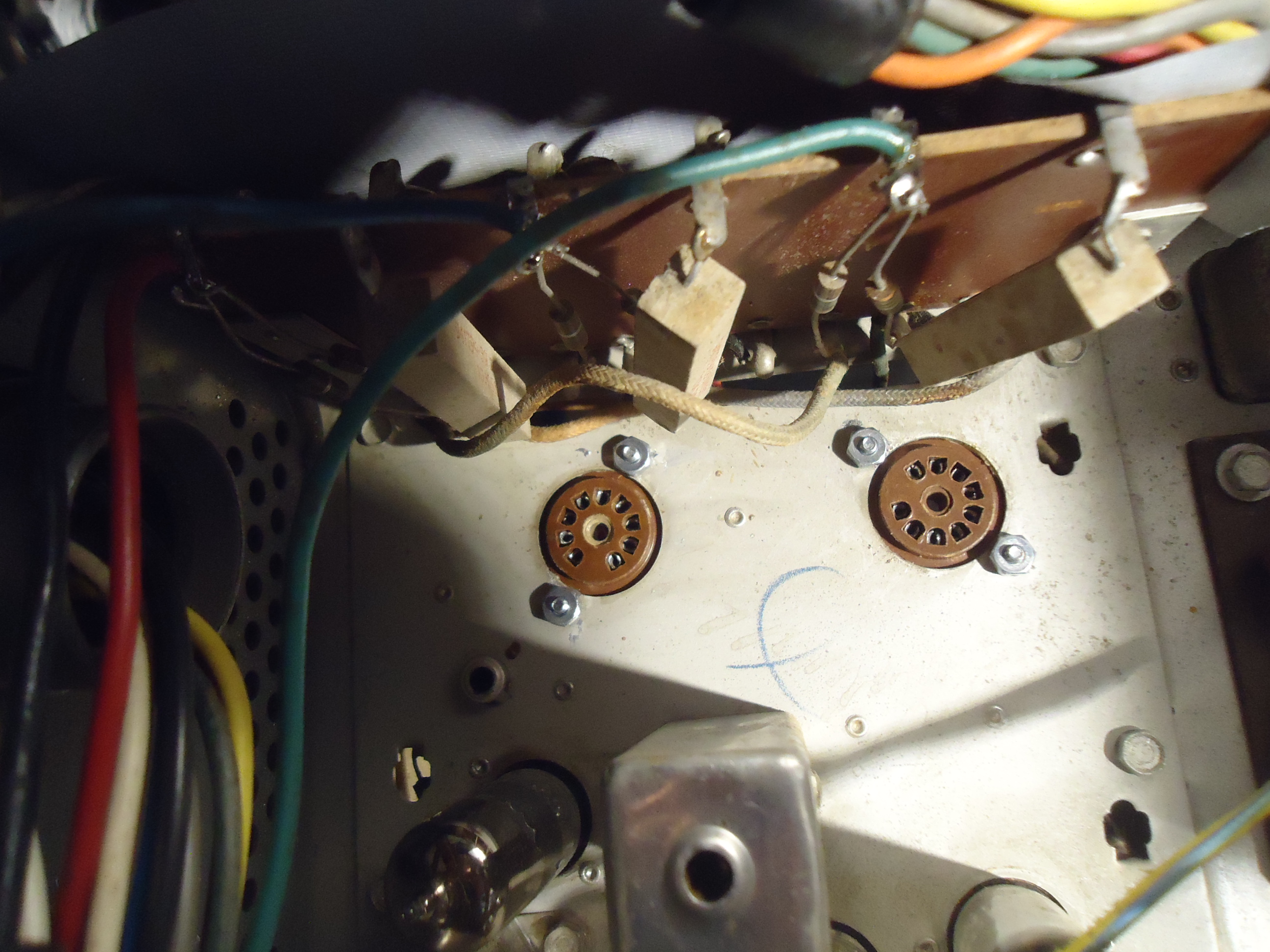
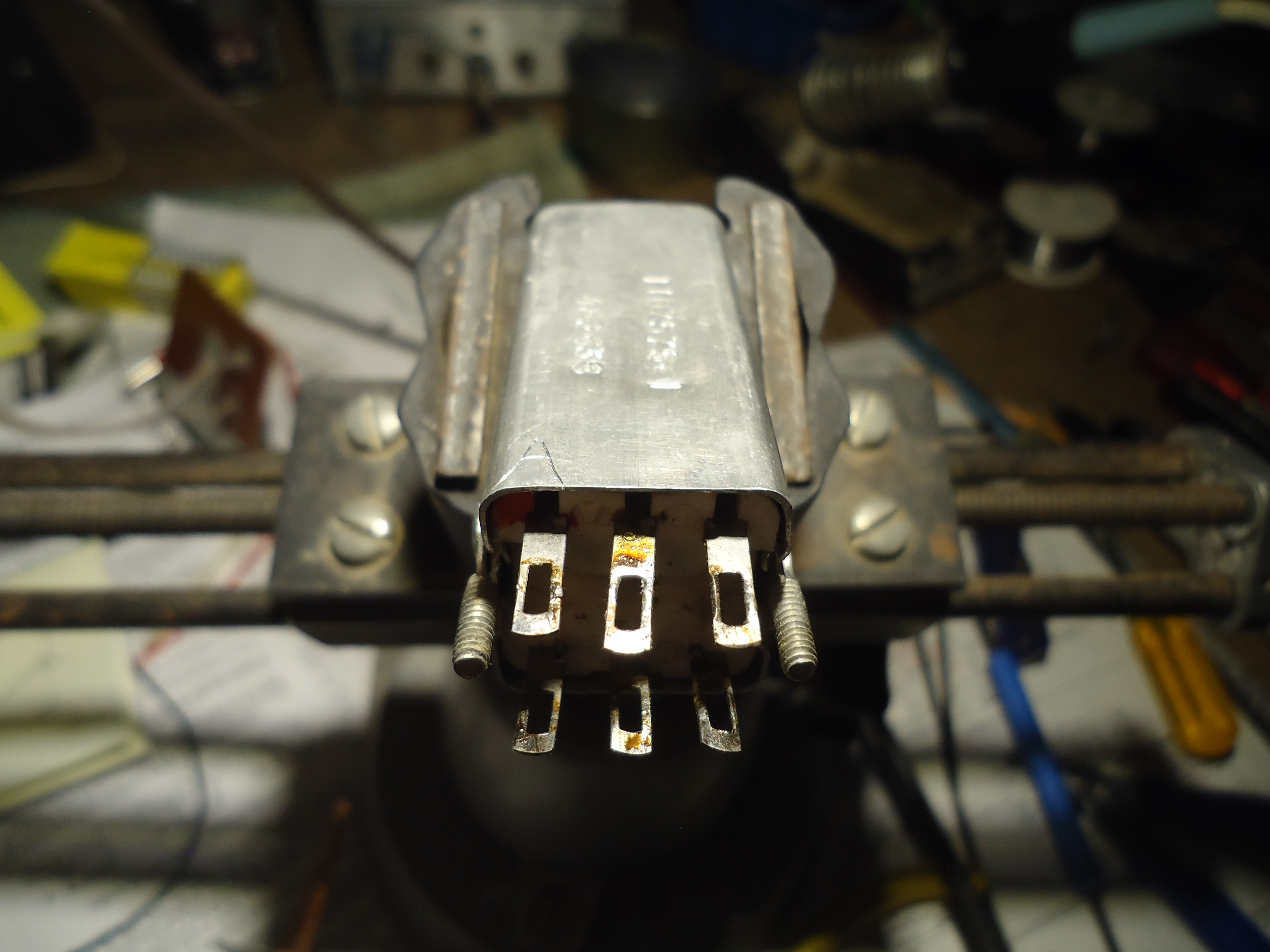
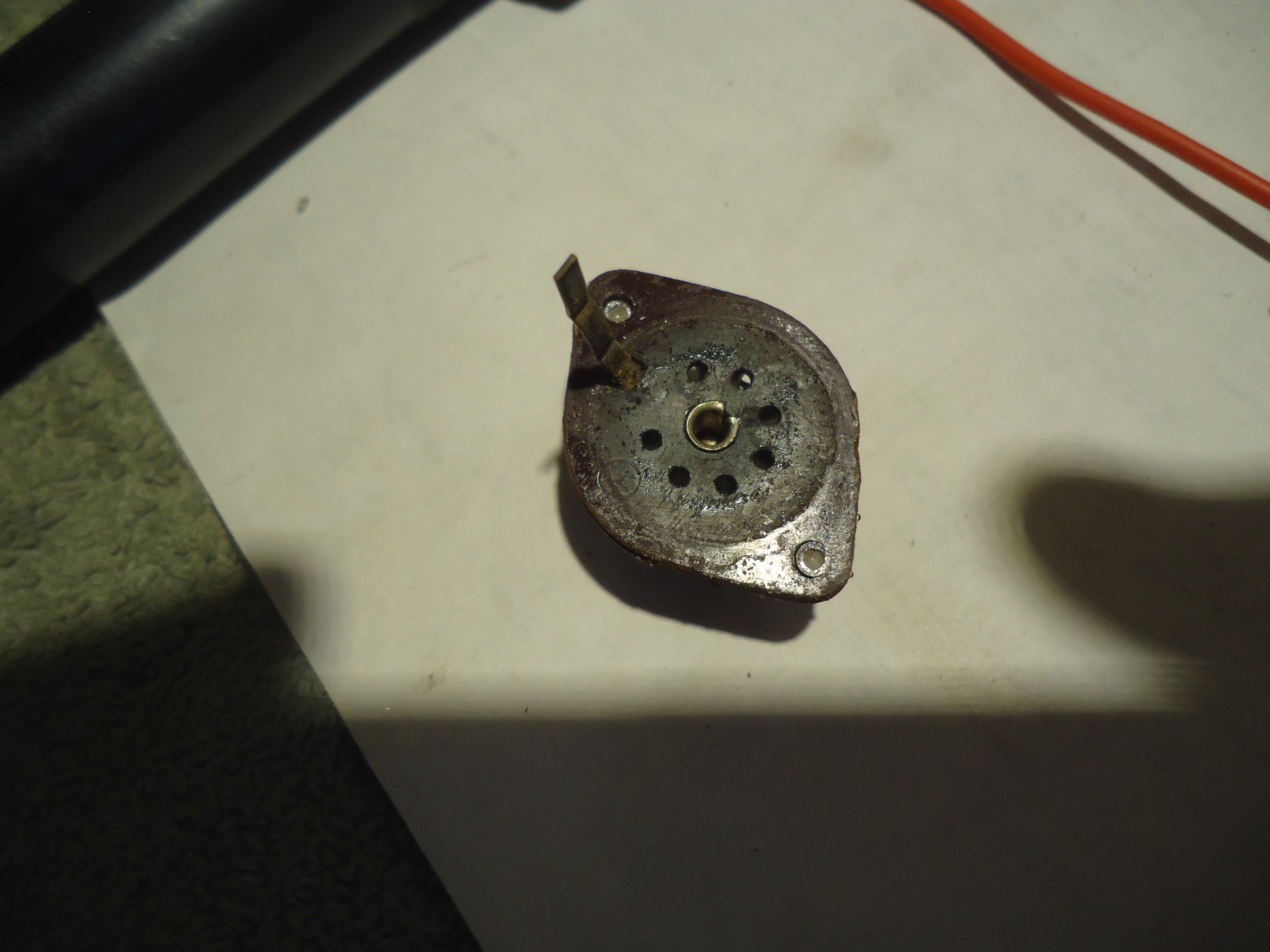
Tonight I was looking at the chroma circuits a bit and noticed that the R-Y, B-Y and G-Y tube sockets need to be replaced. They are very brittle and have intermittent tube socket connections from many years of heat from the tubes. More on that later.
Cheers, Mike
December 9, 2024
Update.
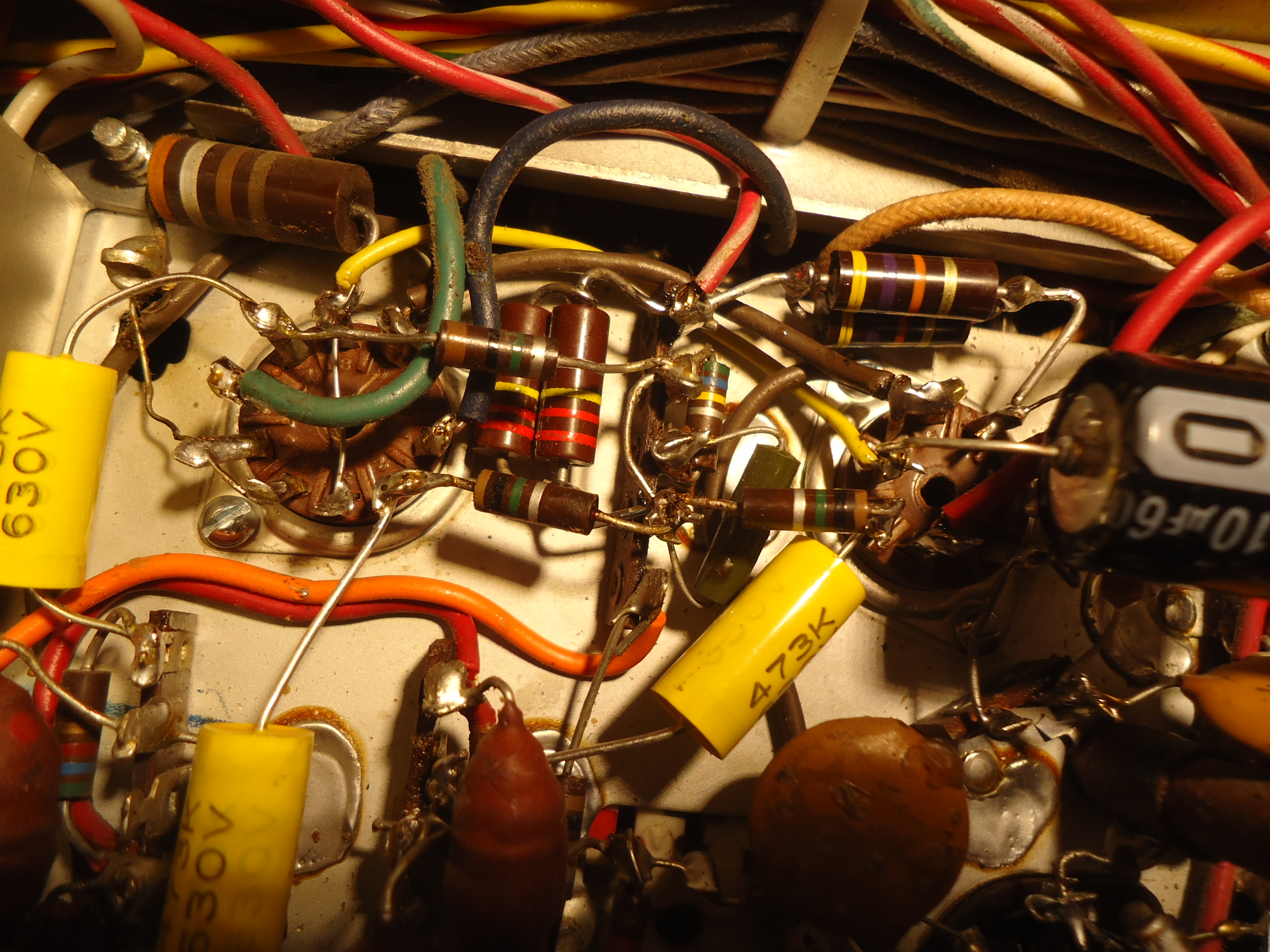
Greetings. I have done many things on the restoration since my last report. A lot of time has been spent on the restoration of the Chroma Circuits. What a mess. But first, let me recap on the last report with details. The first picture will be of the mods in the power supply. Top of chassis showing the two 5U4’s removed and replaced with 1 “plug in” using solid state 1n4007 rectifiers. Also, along side is the 70 ohm 50 watt chassis mount resistor to take care of the increased voltage that resulted in the mod. I also replaced a dual potentiometer for the red/green dynamic convergence. No picture for that. The green section was beyond cleaning. I had a good spare unit in my CTC5 Junk.
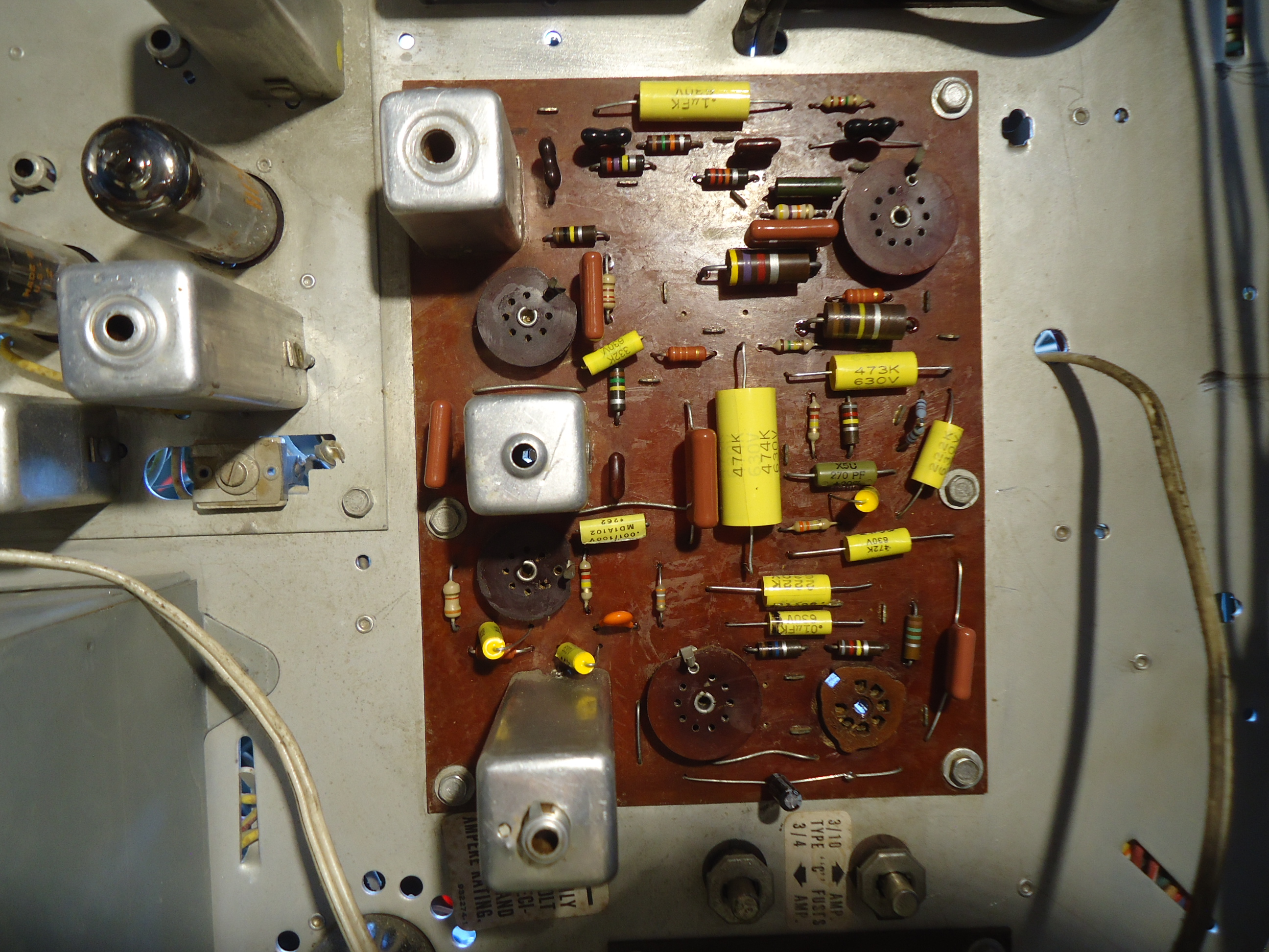
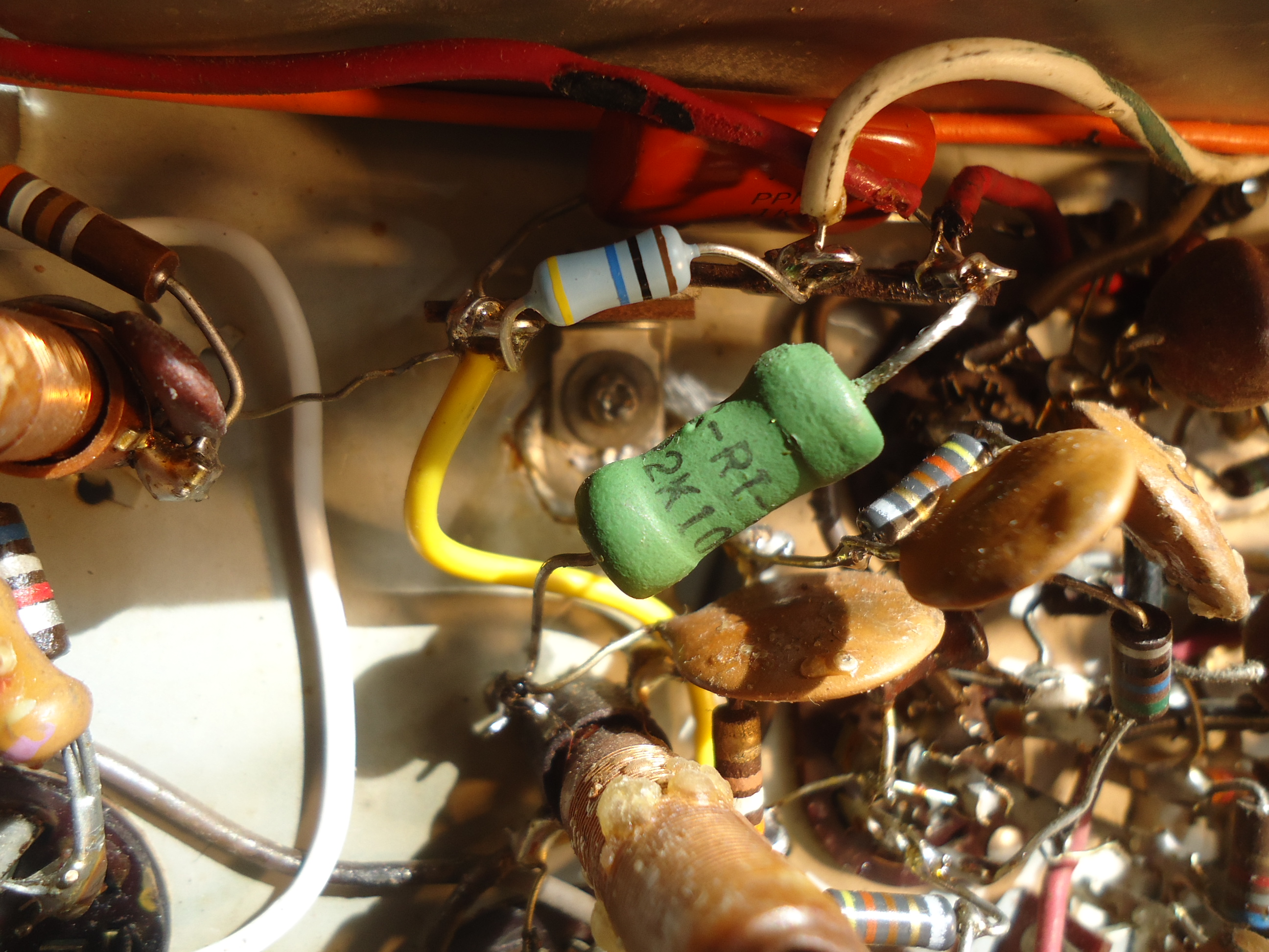
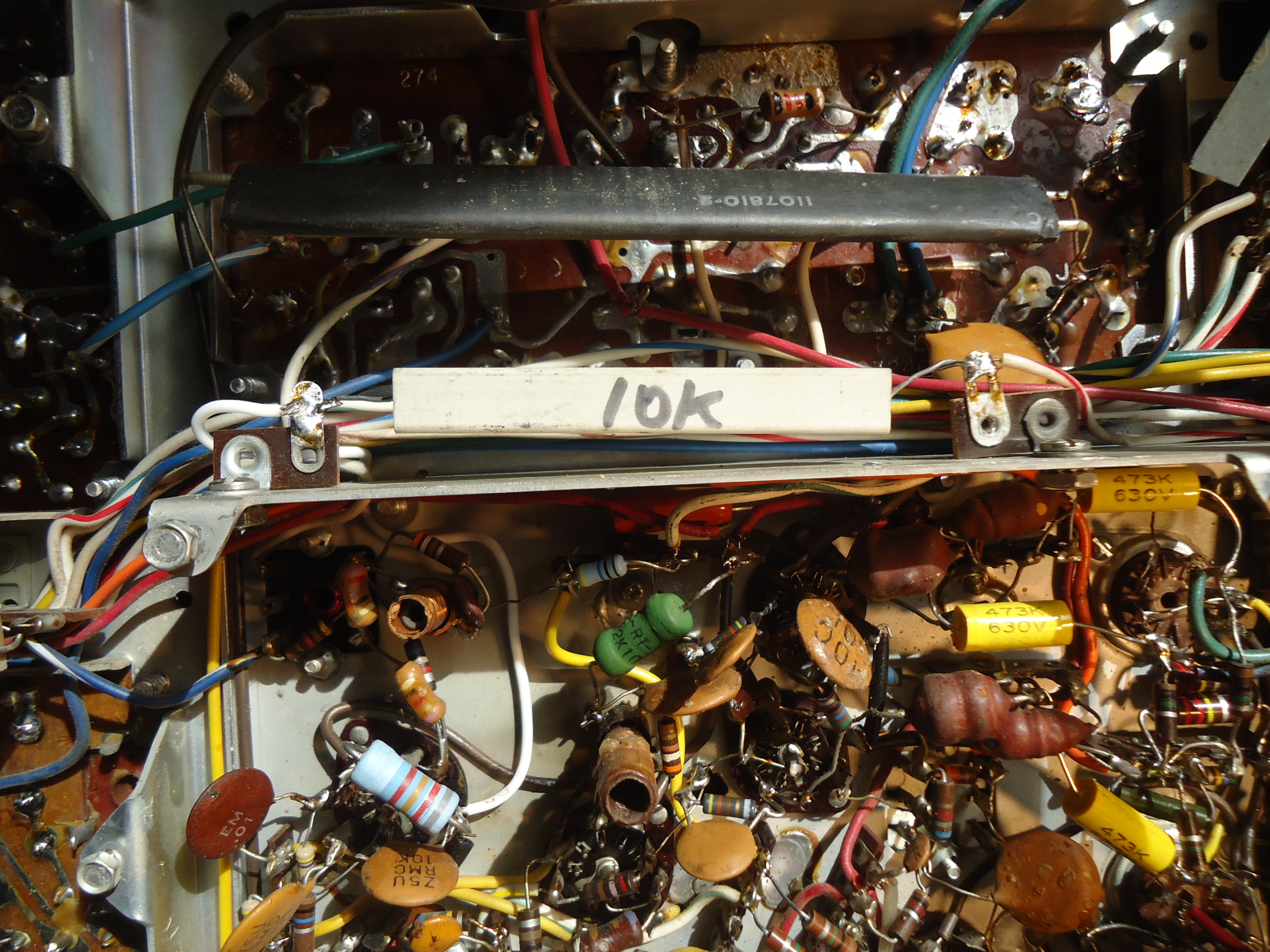
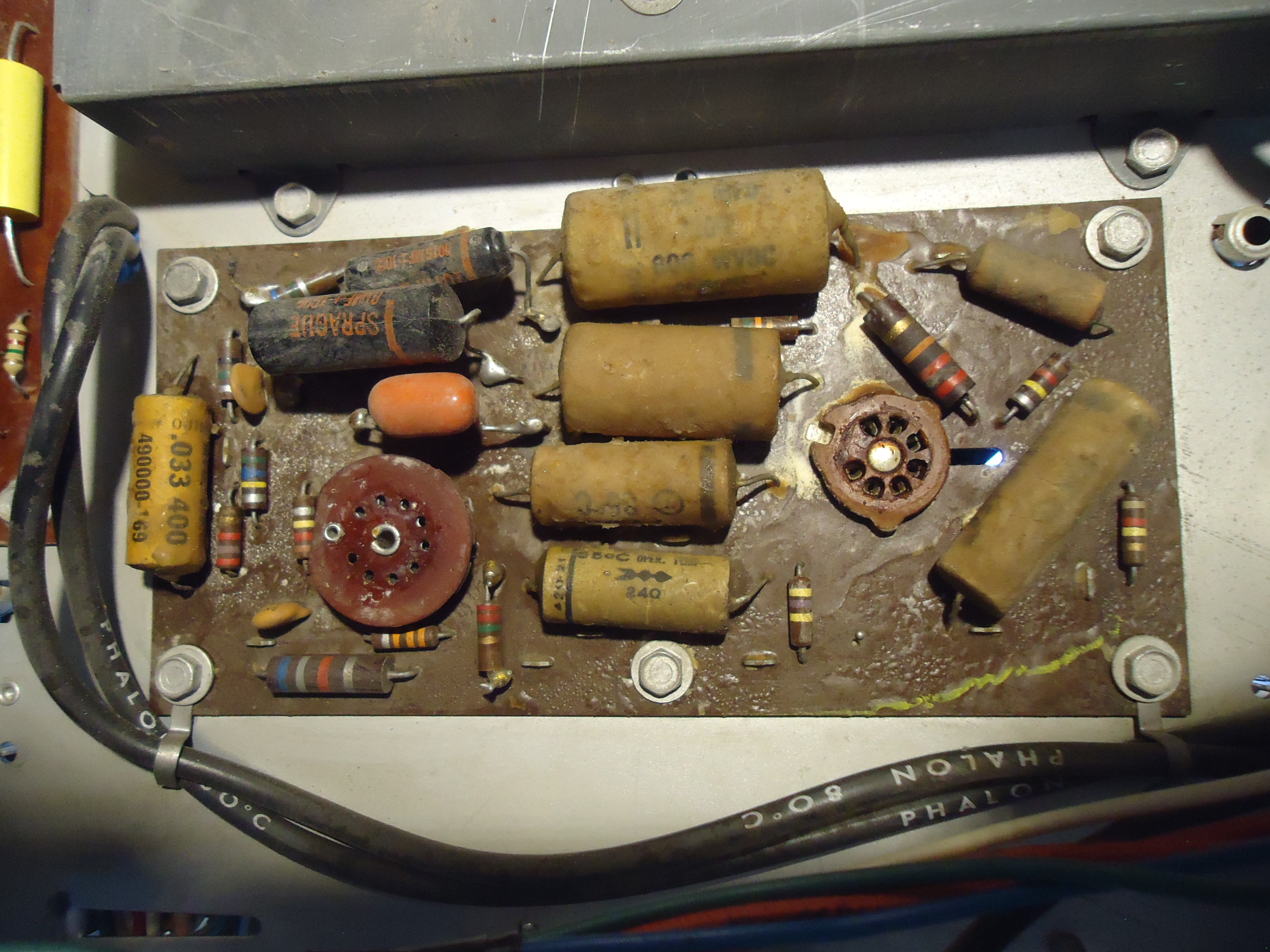
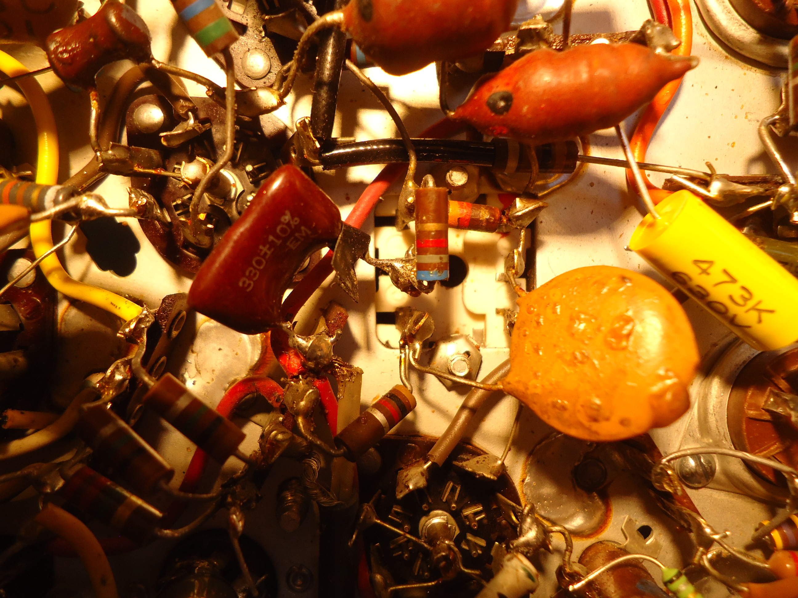
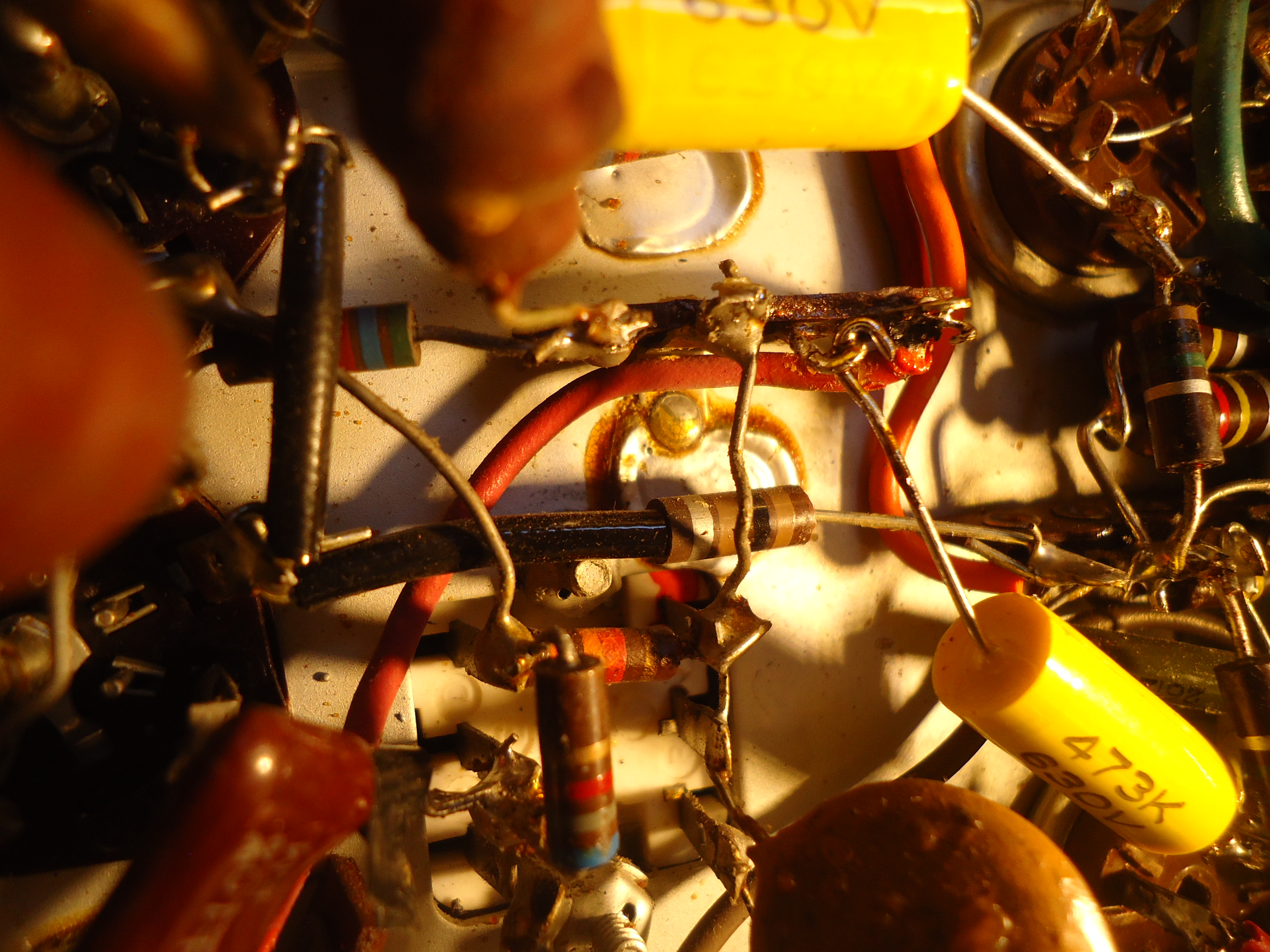
OK, now to the Chroma Circuits. There have been a number of things to address. One, problem was that the gray scale changed every time I fired up the chassis. Then it would slowly change from red, to green, to blue slowly, then any color and back again. This usually resembles a failing CRT, which is not the case here. I traced this problem to the tube sockets of the R-Y, G-Y, and B-Y / Blanker tubes. (12BH7’s). The filaments were changing in brightness. It was necessary to replace both of those tube sockets. The gray scale is now stable. Another issue with the Chroma rebuilding was a failing terminal strip. In the picture, this can be seen above center in the full view photo. Also shown close up in another photo. The terminal strip overheats due to a big 10 Kohm 10 watt resistor that never should have been installed there. I have moved it to just above the chroma circuits, and away from the sensitive tuned coils. It can be seen in the full view photo just left of center. It looks like a cement rectangle. In the later photo, it is missing because I moved it out and away from the Chroma Circuits. and you can see where I replaced a burned wire with a new white wire. I replaced a lot of resistors that were way out of tolerance, and of course all wax type capacitors.
Photo 1 5U4 tubes removed and solid state rects installed. Also, 70 ohm 50 watt resistor chassis mounted for heat dissipation.
Photo 2 Chroma strip charred
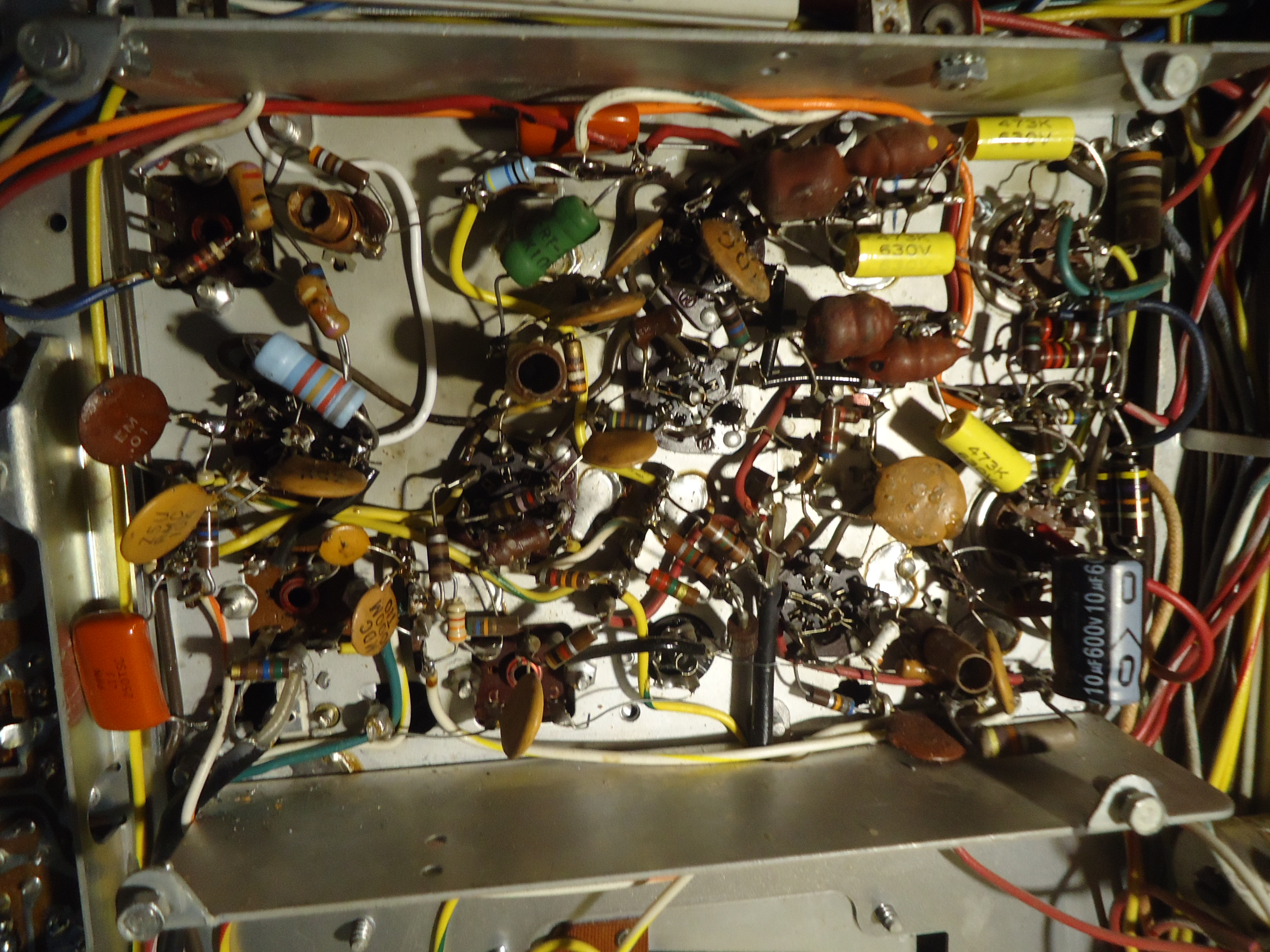
Photo 3 Chroma Circuits b4 component upgrades.
Photo 4 Chroma strip replaced
Photo 5 Relocation of the 10 K ohm 10 watt resistor
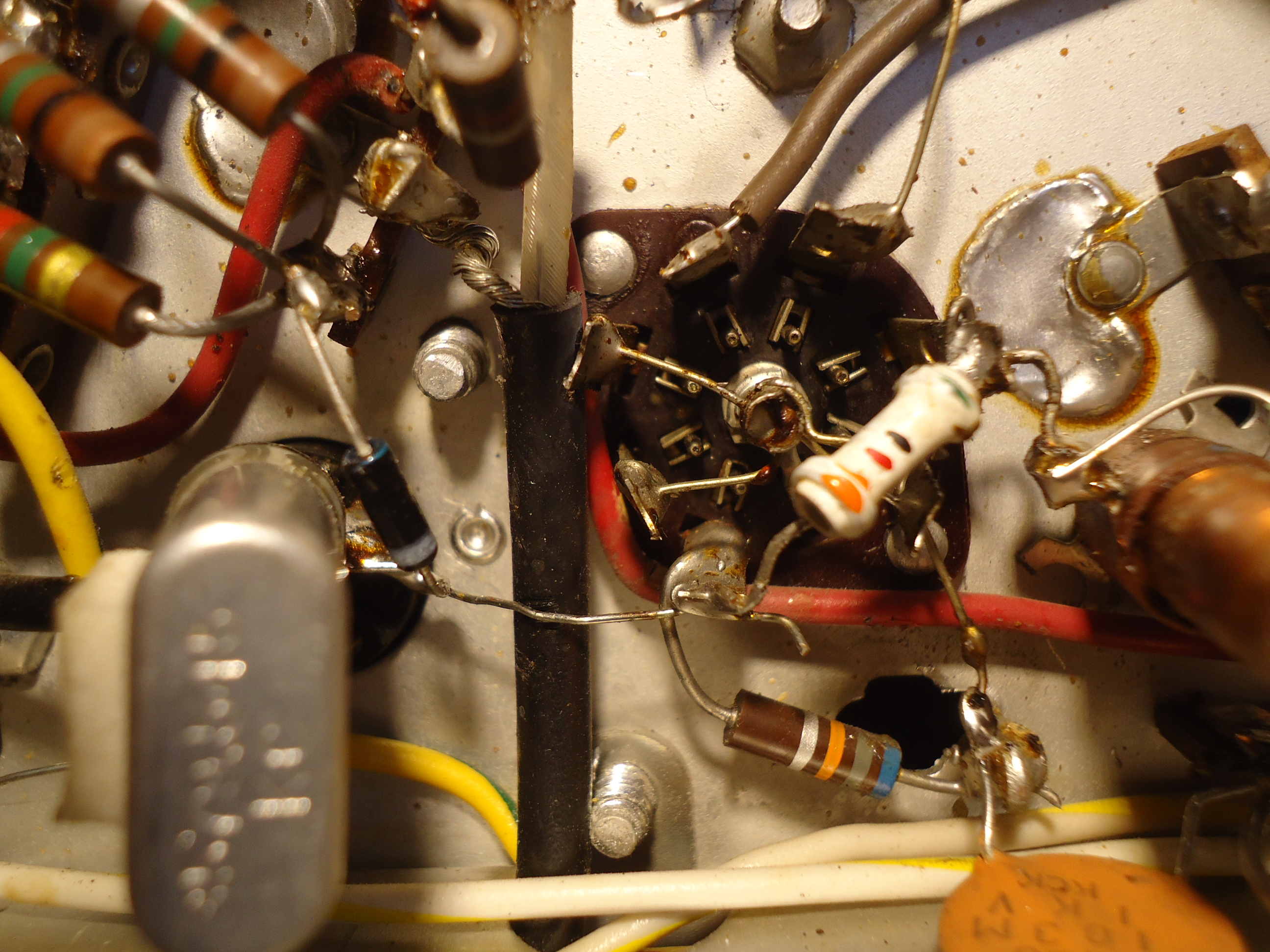
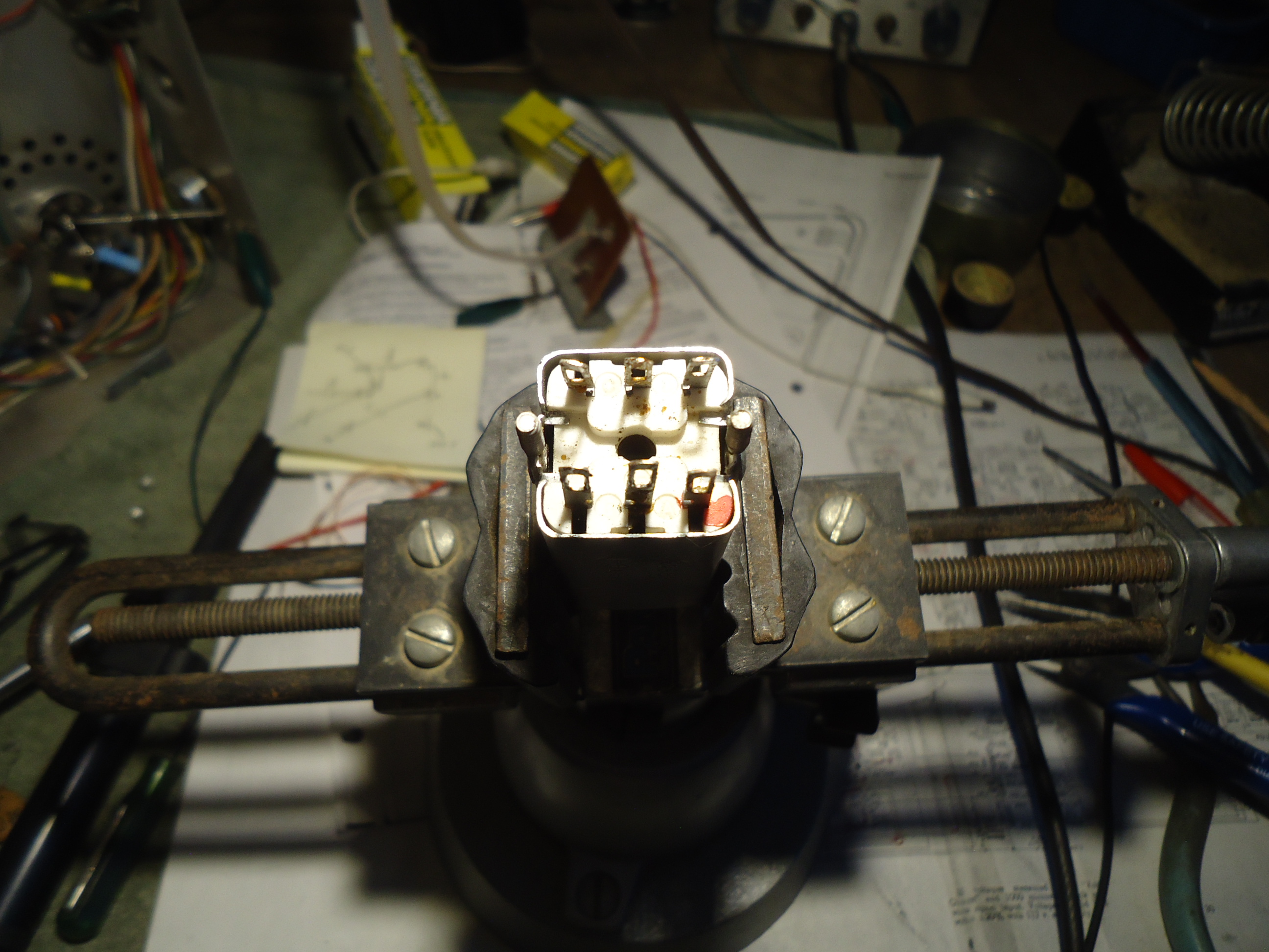
Photo 6 Replacement of the 2 tube sockets bottom view
Photo 7 Replacement of the 2 tube sockets top view
Photo 8 The Chroma Circuits finished with rebuild
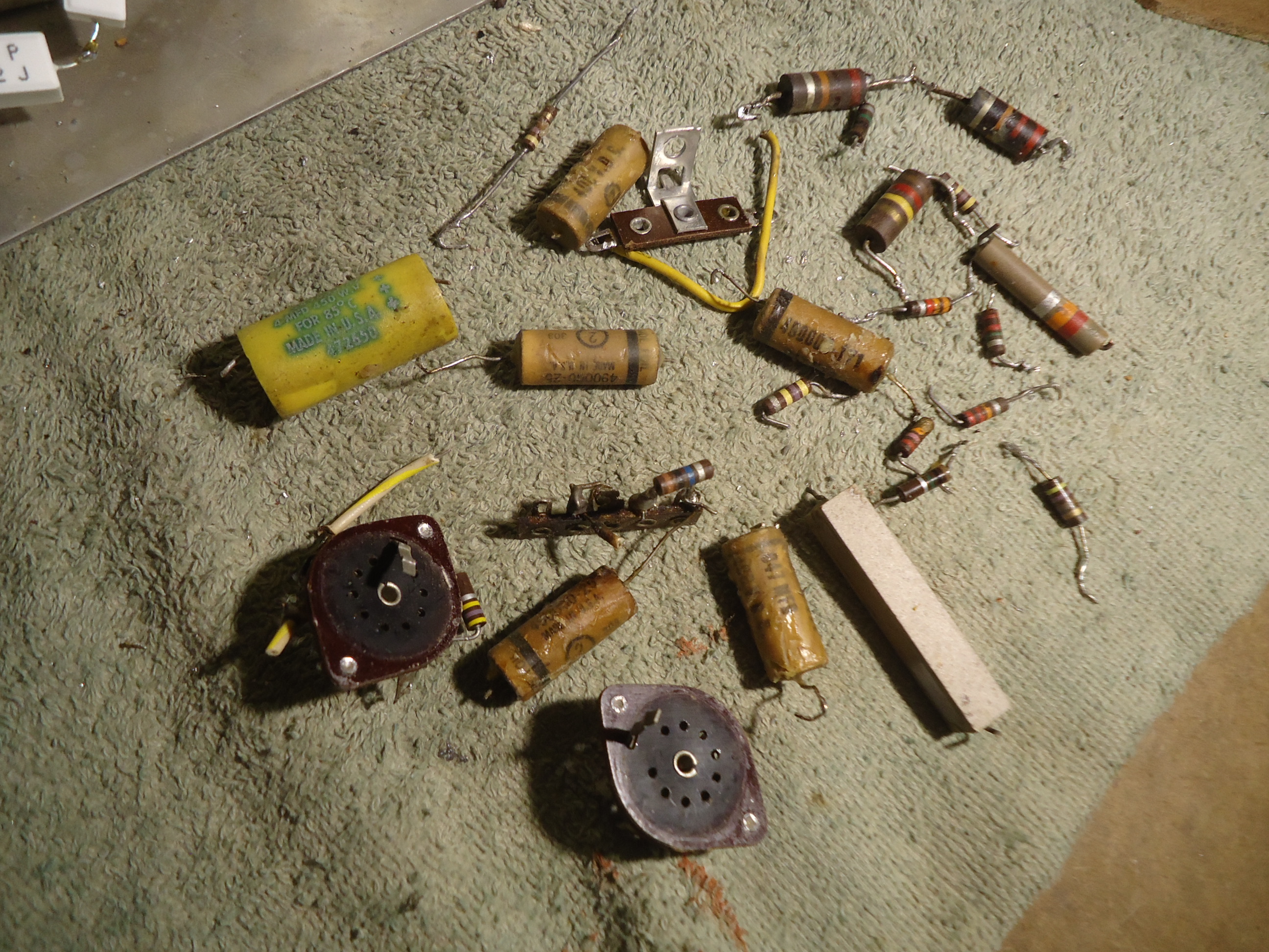
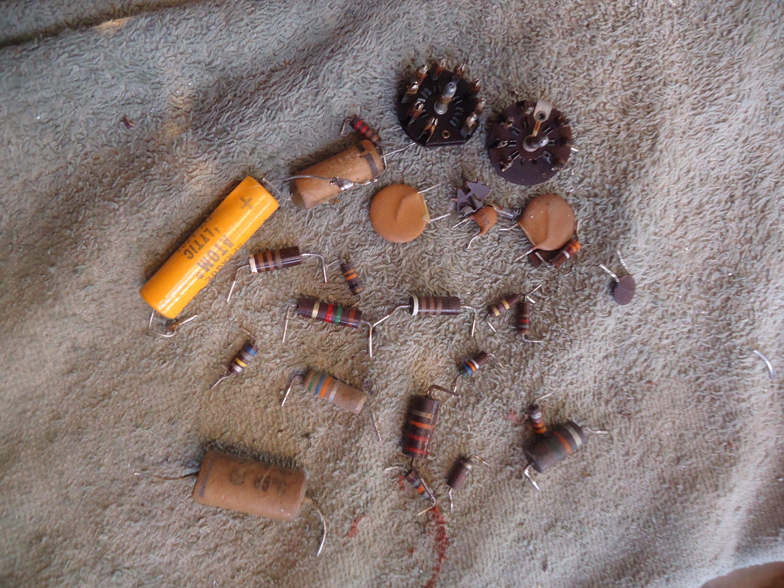
Photo 9 All the components that I replaced in the Chroma Circuits.
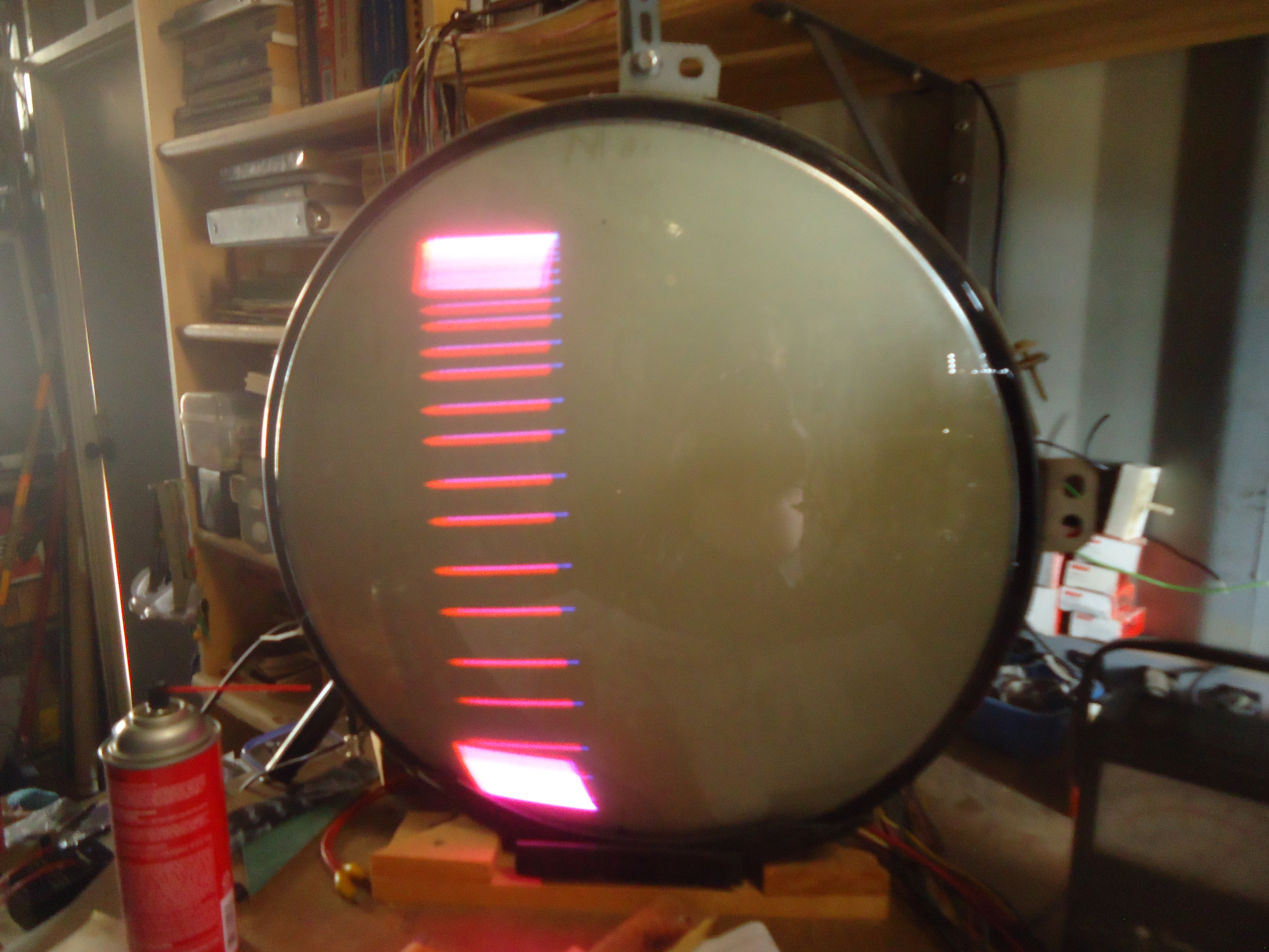
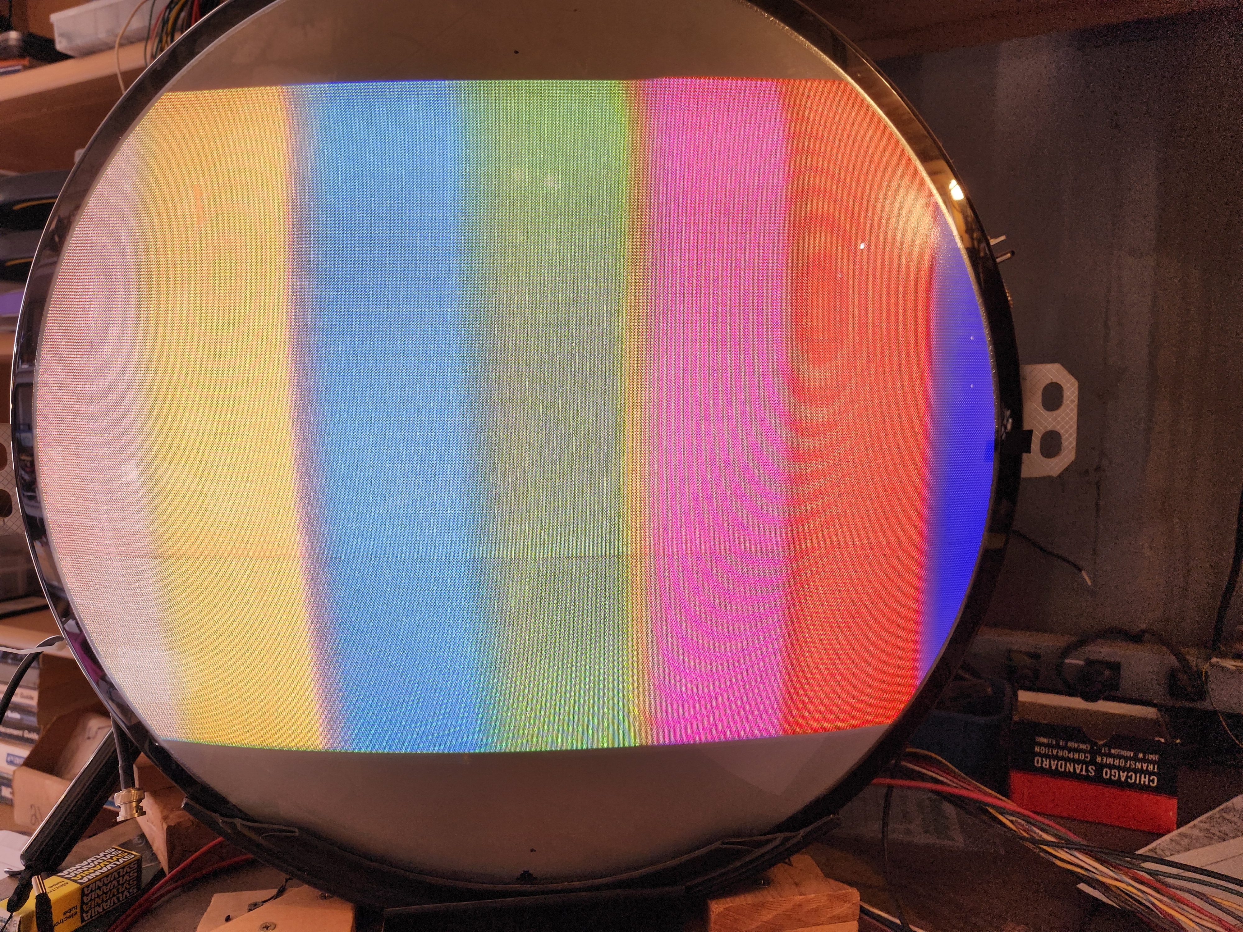
Photo 10 CTC5 Color pattern when finished with Chroma Circuits.
Next is the Vertical sweep board.
Update, December 22, 2024
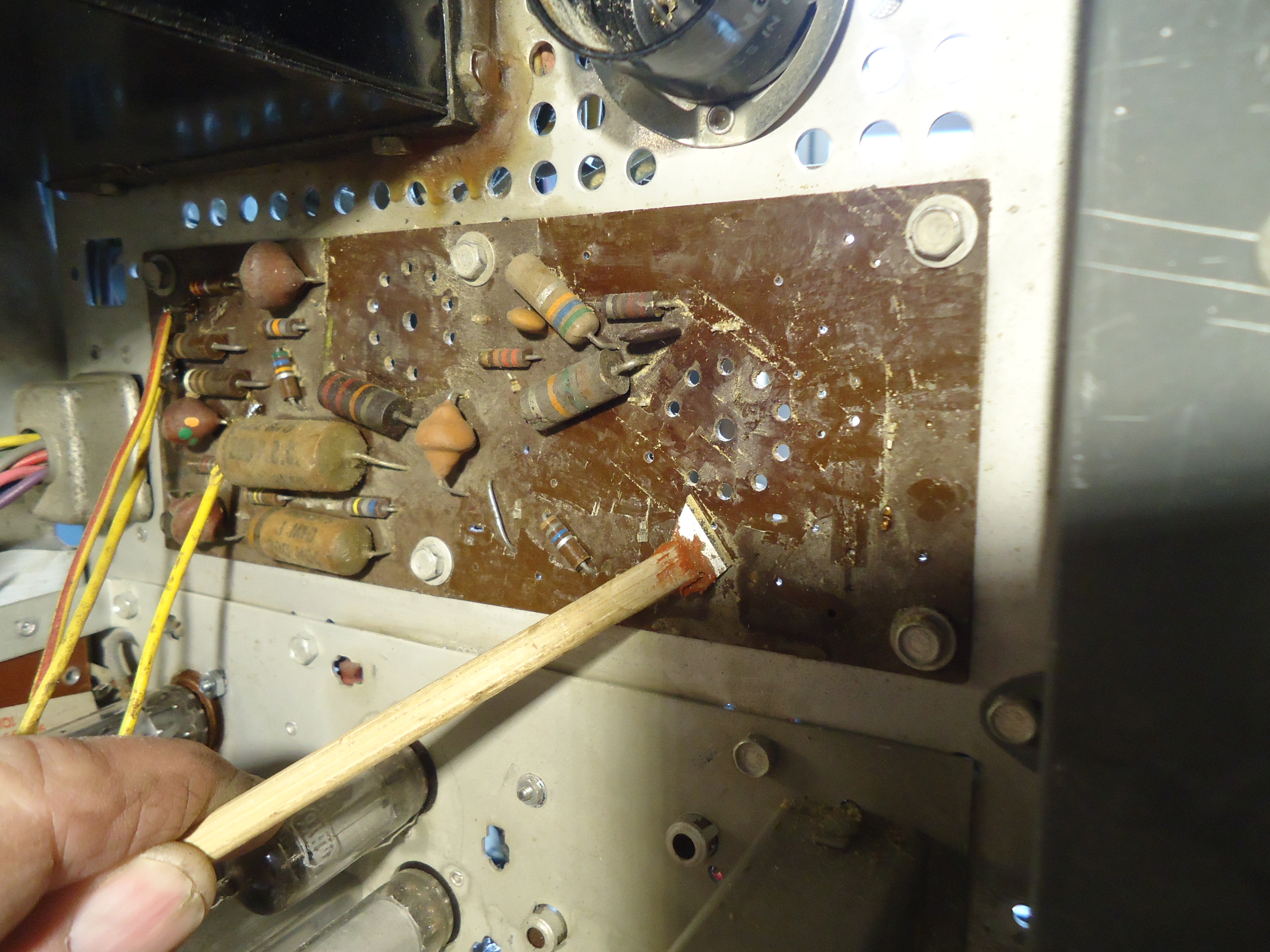
Greetings Marshall. More progress here. I finished the rebuild of the vertical/sync board. I ended up replacing every component on the board, including the 7 pin socket for the Vert. Output tube 6AQ5. The socket pins were badly corroded. I will report now, that on every board, there has been some kind of crusty film that needed to be removed. I am not sure what it was but I did a lot of scraping with a small razor tool that I made on the end of a stick to aid the process. Perhaps some kind of chemical that was used by a previous tech, just not sure. I have never seen this before but it is on every board. Again, too there were a number of out of spec resistors on the vertical/sync board. I have started on the video board this evening but no pictures on that one yet. But I can tell you that both of those tube sockets will need to be replaced as well. I get the feeling that this set spent a lot of time in a warm room and was left on for many hours at a time since the tube sockets are cracking from the many years of heat from the tubes. Maybe in a Hotel lobby environment, or something like that, to make an educated guess? Long story short, this set has had a lot of use. Many components out of spec, and many repairs, some of which were not professionally done. You can see a bit of this mess on the picture of the Vert/sync board where components were tacked on top of the board and not installed directly to the holes in the board. Not good practice. OK, here we go with the new pictures.
Pix 1 Vertical/sync board before rebuild
Pix 2 Vertical/sync board after rebuild
Pix 3 Parts replaced on the board
Happy and safe Holidays and a good New Year!
Mike
Good day Mike,
That first pic, what a mess! Beautiful, close to pristine wood cabinet, but a horror show chassis. We have a good 21AXP22, that says something.
Best holiday wishes to you and yours,
Update, January 20, 2025
From Mike,
I have done a complete rebuild of the Video Board. All components were replaced since I had to do a full scrape of the top of the board to remove some kind of residue from previous repairs. Not sure what this stuff is, but it is not rosin from a solder bath treatment. I have found it on all of the P.C. boards of this chassis. I made a special tool from a small razor blade to help in the process. Also, both tube sockets needed to be replaced. They were both crystalized from heat and the socket pins were exposed from the top of the board. I removed the top cover of the I.F. board and it appears to be clear of this strange residue. I notice a small crack on the I.F. board where one of the mounting screws secures it to the chassis. Fortunately it is not in a critical place of the electronics. It is only a ground, and the ground is good. It bothers me a bit though, that this made it through the assembly line without being caught. However, before this chassis is finished, I will be beefing up all of the grounds on the P.C. boards with wire soldered to the chassis from ground points on the boards. This insures a good ground from P.C. board to chassis. From the looks of the I.F. board, there will not be too much to do in the way of component replacement. I may replace both the Audio and Video detector diodes due to their age but that will probably be all unless I run in to some surprises during R.F.I.F. allingnment.
The picures are as follows:
Pix 1 Video Board before rebuild
Pix 2 Scraping with tool.
Pix 3 Sockets removed and board 1/2 scraped of residue.
Pix 4 Parts replced on Video Board
Pix 5 Video Board after rebuild
Pix 6 Video Board after rebuild with tubes installed.
Pix 7 I.F. top of board with cover removed
Pix 8 I.F. board with crack at mounting bolt.
Yet to do:
Add grounds to P.C. boards.
Replace several more caps in main chassis
Make screws for Yoke Clamp. “special”
Make up a back cover.
Add H.V. cover that is missing.
Do AFPC alignment of Chroma Circuits
Do R.F. I.F. alingment check and adjust as needed.
Cheers, Mike


Update, January 29, 2025
From Mike,
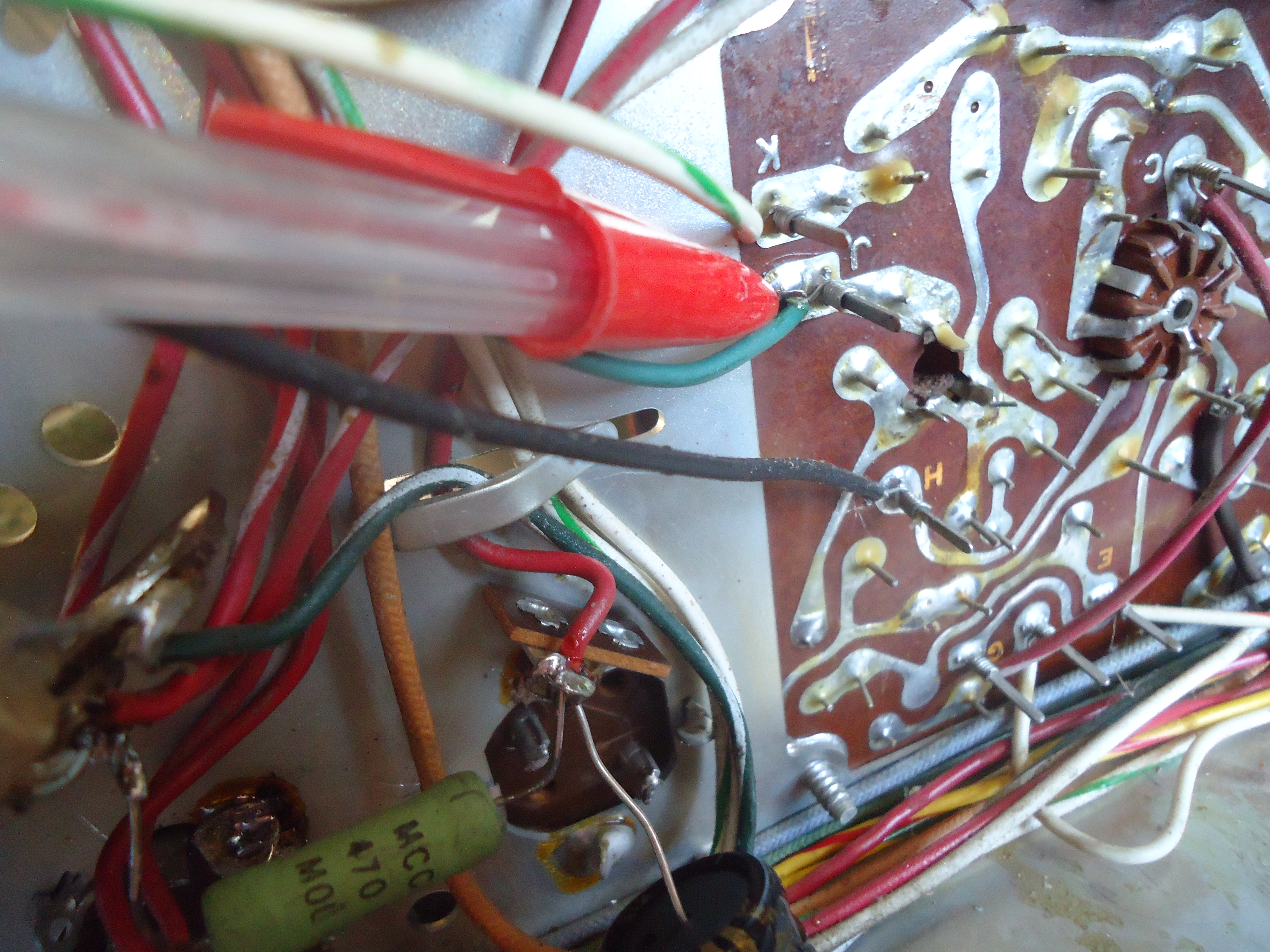
Greetiings once again. I have added ground wires to the necessary boards but no pictures on that. Not much to it really. I have moved to the high voltage cage to change several caps in the horizontal centering circuits. In the process, I found a number of issues that needed to be addressed in the focus circuit. There was an extra resistor installed that really should not be there. It wasn’t hurting the operation but it was poorly installed and had no purpose so I removed it. Also, there was a resistor missing in the voltage divider for the focus voltage. Seemingly, there was also an extra resistor going to nothing as well. I also removed that one. I used the terminals that were freed from that removal to install the missing 2 meg 2 watt resistor that should be there for the voltage divider. Not sure what all of that was about. ?????? I also discovered some poor wiring on the focus control. A “cold” solder joint that was obviously intermittent mechanically. I replaced all of the wiring on the focus control to original specs. I observed some wax leakage from the flyback and removed what was easy to remove.
The pictures are as follows.
Pix 1 Top of chassis with all boards rebuilt
Pix 2 Chassis bottom without the covers installed yet. (Later)
Pix 3 Focus control circuit with extra 56 K ohm resistor
Pix 4 H.V. Section before repairs
Pix 5 Wax from flyback transformer
Pix 6 Cold/poor solder joint on focus control
Pix 7 330 K ohm resistor not connected to anything with black focus crt wire mis-wired.
Pix 8 Chassis shot of flyback
Pix 9 Caps replaced, wiring corrected. Notice 1 Meg 2 W resistor added and black focus wire in defferent place
Pix 10 Focus control wiring repaired
Yet to do: The tuner needs attention and I have already started on that.
R.F. I.F. alignment.
AFPC alignment in chroma circuits
Chroma Bandpass alignment
Make extention for back cover
Make new wing bolts for yoke clamp
Whatever else I can think of. There must be more.
Cheers, Mike.
Update, February 14, 2025
Good Morning.
I had to do some work inside the tuner. Two of the B+ power resistors were out of tolerance. The main tuner cover was not installed properly by a past tech so I had to remove the tuner from its mounting assembly and straighten the cover so it fits properly. Also, the cover for the antenna input balun unit was missing.. I had a spare! Here goes with the list of pictures. These will be sent over 3 emails.
Pix 1 Parts replaced in H.V. cage.
Pix 2 Cover missing on Antenna balun unit.
Pix 3 Cover replaced from my spare parts.
Pix 4 Tuner 10 K ohm resistor down in value to 7 K ohm.
Pix 5 Tuner side view with 10K resistor replaced.
Pix 6 Tuner 12 K ohm resistor up to 17 K ohm.
Pix 7 Tuner 12 K ohm resistor wide view.
Pix 8 Parts replaced in tuner.
Update, February 22, 2025
From Mike,
I have changed the video detector diode which improved the contrast by a fair amount. I also changed a similar diode in the color killer section only due to its age. It was the same part number as the video detector, general purpose signal diodes, 1N64. There appears to be a small problem in the chroma phase circuitry where the hue changes by a fair amount as the set warms up. Not sure what that problem is just yet. When I was doing the AFPC alignment (Automatic Frequency and Phase Control) of the chroma circuits, the hue never came out right which indicated a phase problem. This turned out to be the 3.579545 MHZ crystal was slightly off frequency. After replacing the crystal, the AFPC adjustments came out right, but I am still left with the hue change after warmup. More on that later. Another thing that I am not happy with is the resistor in the power supply that I chose to reduce the B+ voltages due to the solid state rectifiers I installed to replace the 5U4 tubes. I have ordered a better replacement for that resistor. I have done a full alignment of the Chroma Bandpass amplifiers and the RFIF strip. Improvements came from both. I will be working on the new special screws for the yoke clamp and the modification of the new back cover which needs to be made wider for the cabinet. Pictures will be sent over 2 emails.
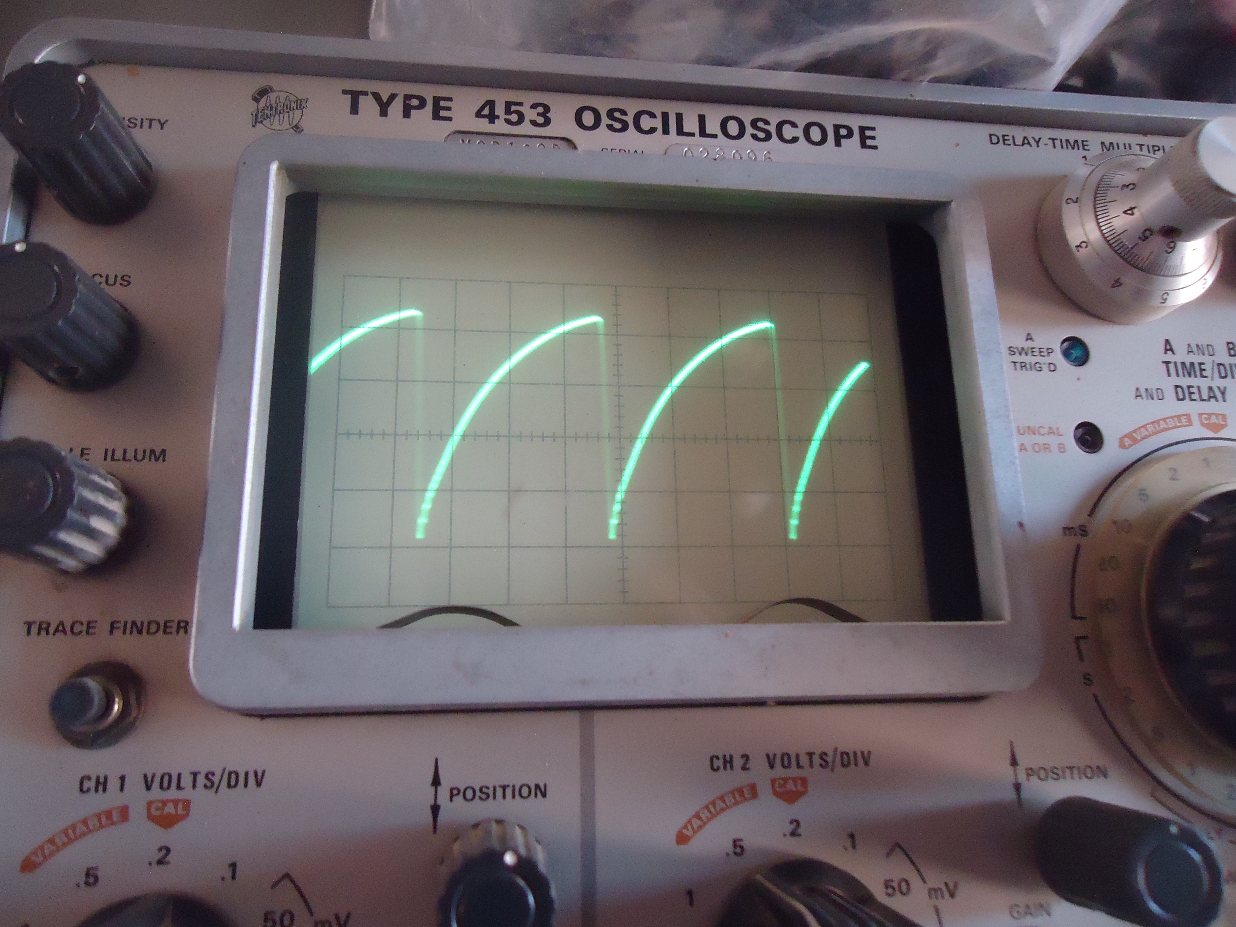
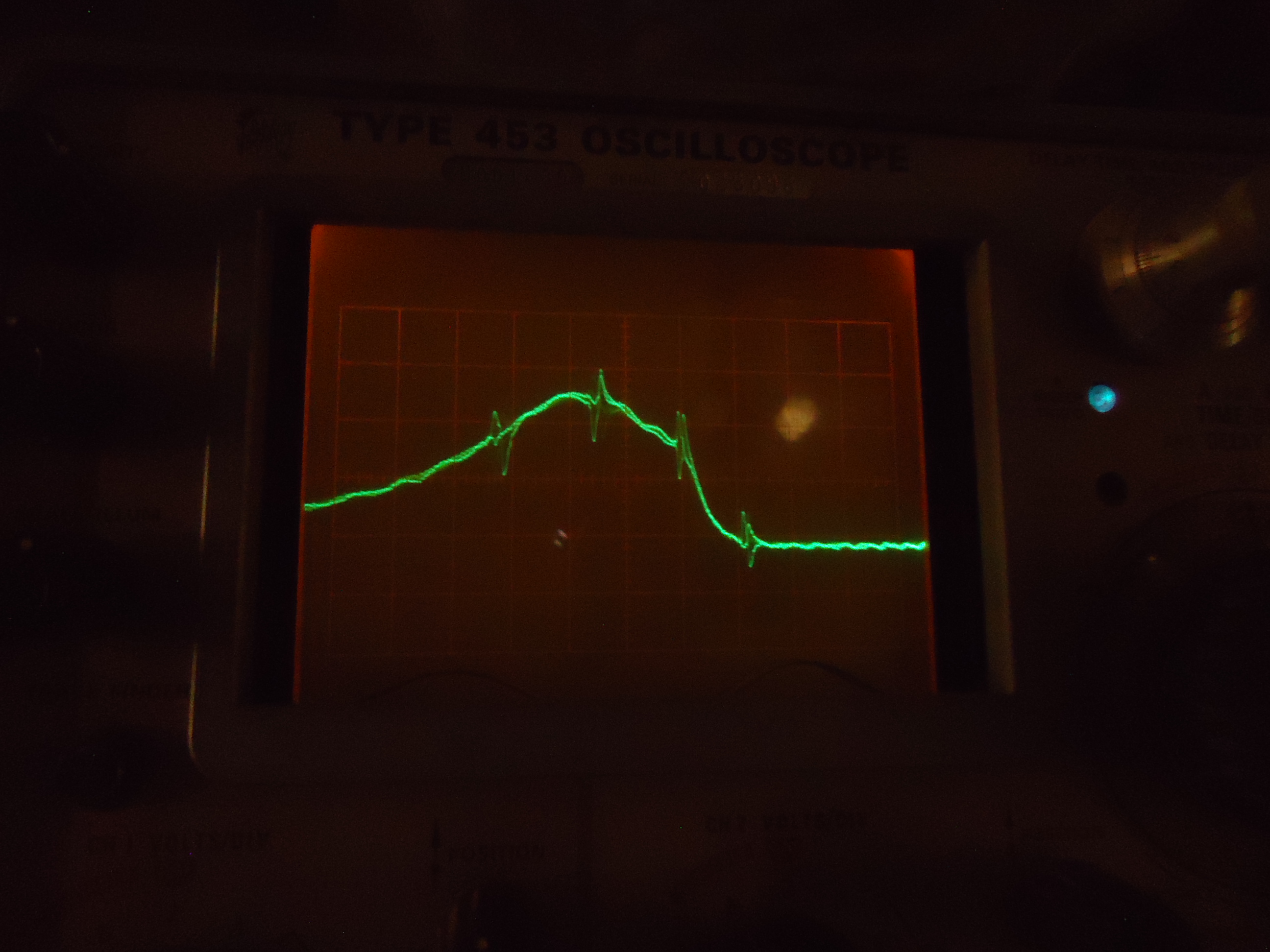
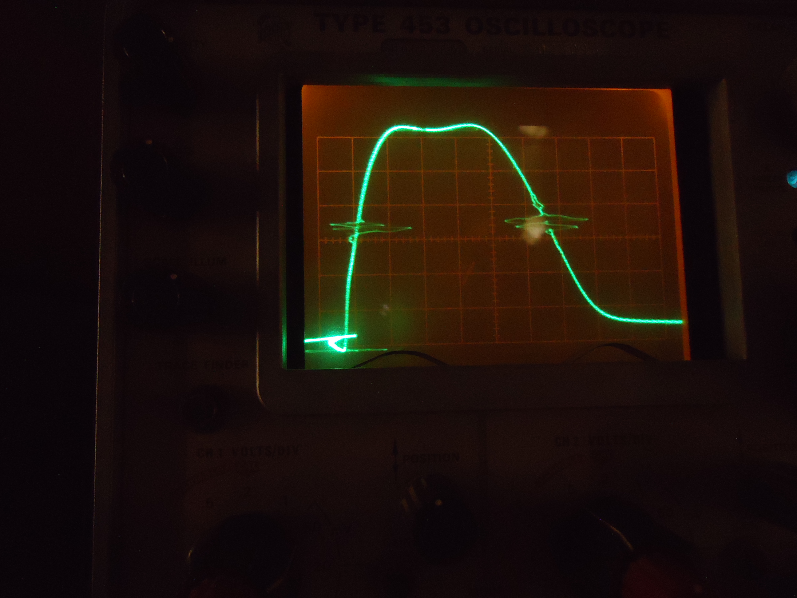
Pix 1 Chroma Bandpass Curve after alignment
Pix 2 R.F. I.F. curve after alignment.
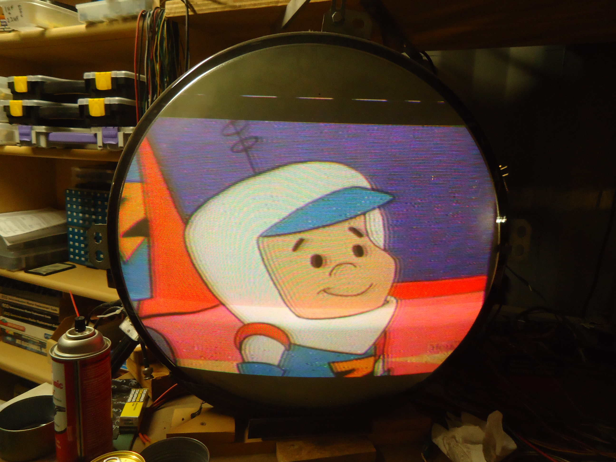
Pix 3 A good Jetsons cartoon shot to show good color.
Pix 4 A shot of a girl from Hawaii 5-“O” w. good yellow!
Pix 5 A shot of a flying helicopter on Hawaii 5-“O”
UPDATE, I changed the Burst Amp transformer and that seems to have fixed the drift. If there is any drift now, it is very minimal. The drift was dramatic b4 the transformer swap. Cheers. Mike.
Update, March 12, 2025
CTC-5 Update
From Mike,
Greetings Marshall. We are in the homestretch with this one. Still some HUE shift but that might be my JIG CRT. Replacing the Burst Transformer helped a lot but still some shift of about a 5 to 10 minute warmup. I will be connecting this chassis to my set 21AXP22 crt within the next 2 days. I hope to get a better idea of its performance from that. I hope the Hue shift goes away with that test. I have installed 2 brand new tubes in the sweep circuit even though the ones in the chassis seemed to be working OK. Those tubes are the Horizontal output and damper tubes. 6CB5 and 6AU4. I did this due to their age. I will keep the old ones for test purposes since they still work properly. I feel better knowing that those tubes in the set are new. The yoke clamping bolts were missing so I had to make new ones. They are unobtainable. I was able to contstruct them from some 10-32 threaded rod, some small nuts and wing nuts. J-B Weld epoxy played a big role in the process. If all goes well I plan on delivery of this by the end of this month. I will figure out timing and let you know soon. I stll have to find or make a new cover for the deflection yoke since it has deteriorated over the years. I have a plan in place for that. As for the back cover, I will be finishing that at your house and I will bring all of the materials and tooling to do so. The measurements are still a bit unclear so I think that doing it there is best. I have found the proper chassis bolts so that is no longer an issue. I think the “pencil box” screws are missing also so I will be bringing those too.
Pix 1 is what the original yoke clamp bolts look like. I took this one from my set for the photo
Pix 2 is the 2 that I have fabricated for your set.
See you soon.
Cheers, Mike.


The Plan
March 22, 2025
Hello again. Well, things have slipped a bit with the delivery timing. I have been pulled a lot of different directions this month. It is looking more like the first week in April. I have not had time to bring the chassis into the house and connect it to my tube for final evaluation and that really needs to be done. I keep running the chassis on the bench when I am in the shop and it is still rock solid. I may go through the AFPC alignment one more time on the chroma circuits to see if the slight drift in HUE tightens up. Again, I will know a lot more about that when I hook it up in the house. It all may be my jig CRT drifting. Either way, see you soon.
Mike
Update June 27, 2025
From Mike,
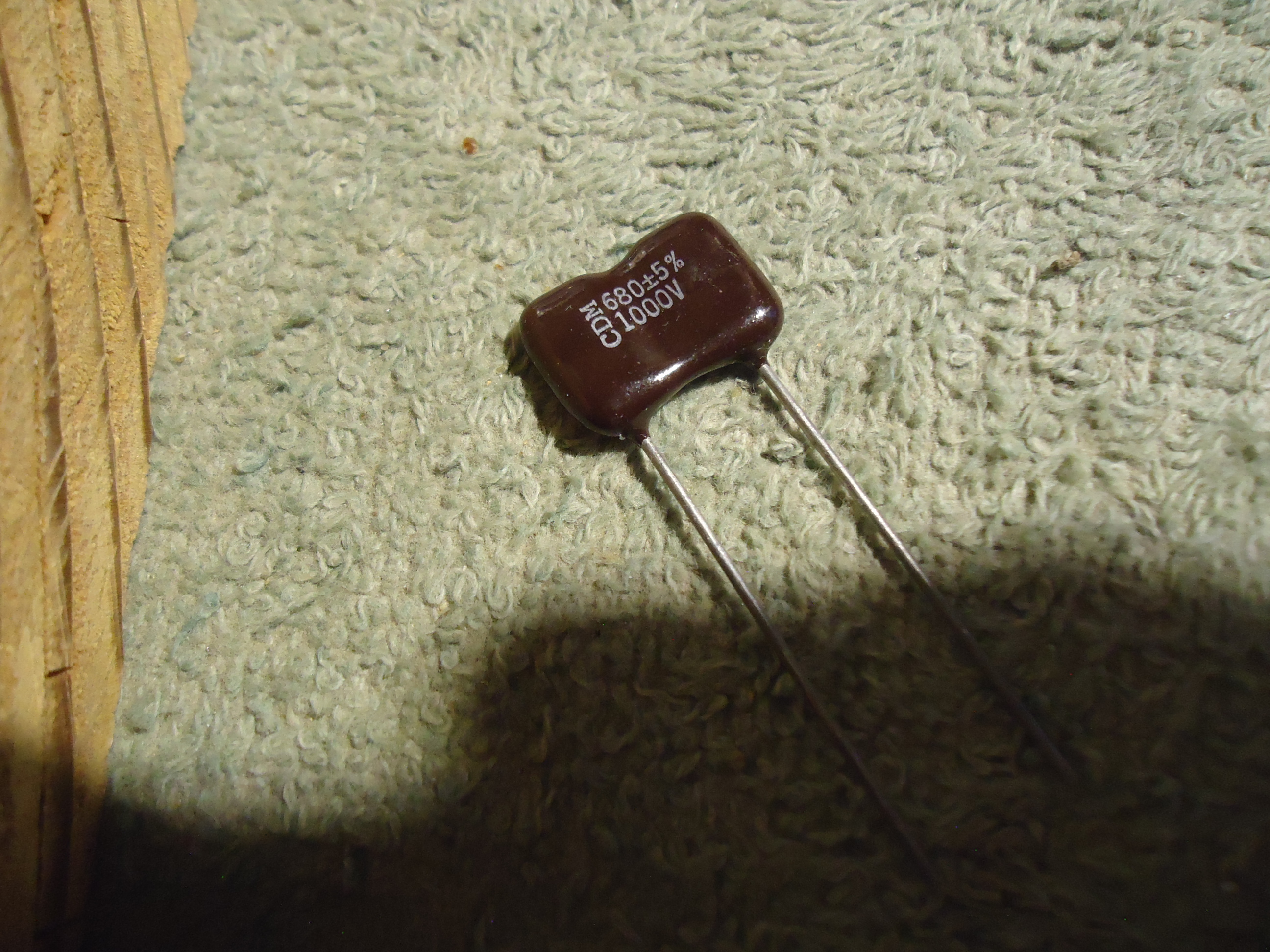
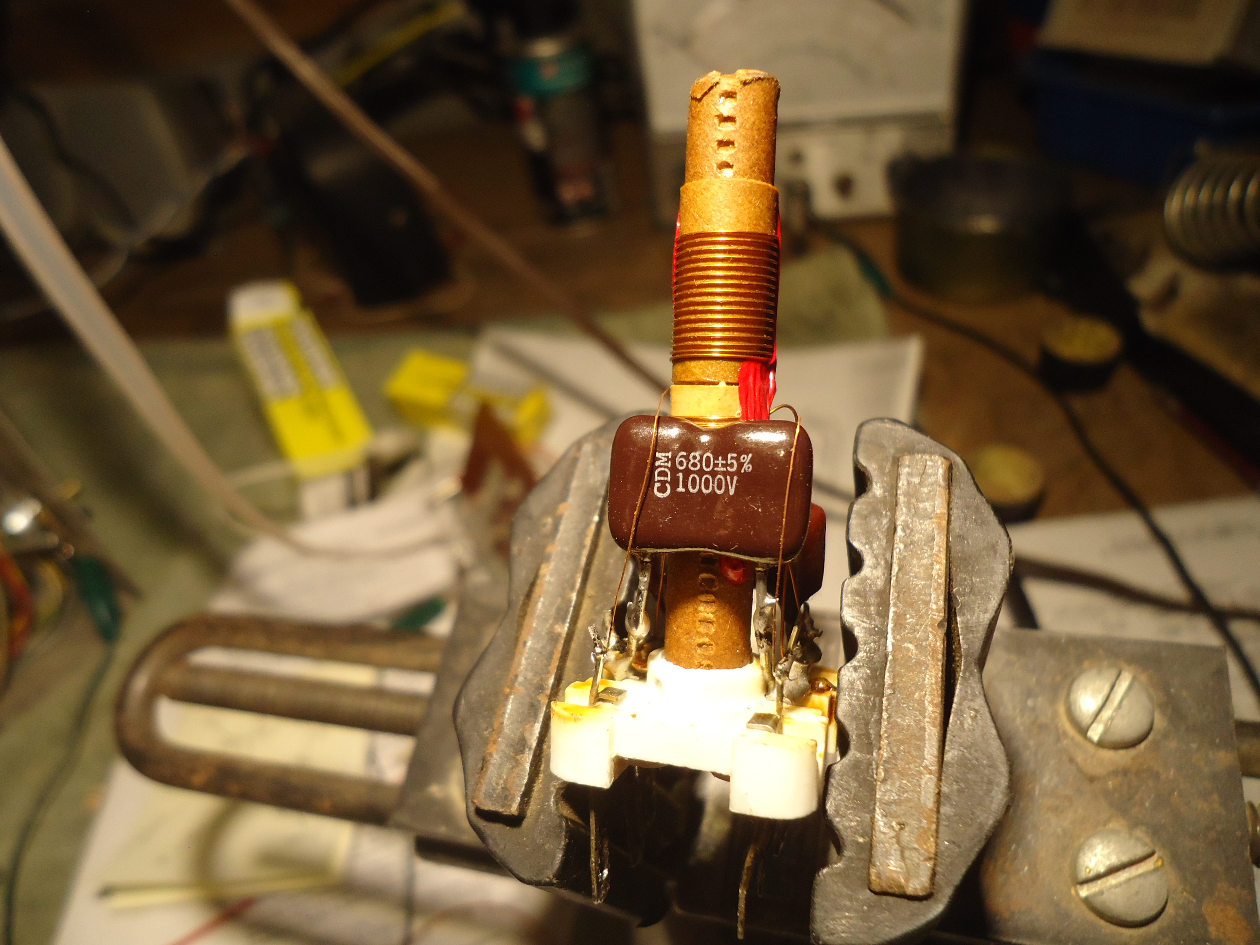
Greetings. After taking about 6 weeks off, it is time to re-visit this project. There appears to still be a shift in the hue. Cold spray has shown no sensitive components. However, there are 2 capacitors located inside the CW Driver Transformer can. They cannot be accessed with the cold spray so I have elected to change them. I had to order these since they are 5% tolerance and the best I could do is 10% in my stock. There are 2 capacitors in the can, a 680 pf and a 1000 pf both of the silver mica type. The wires on this transformer are very small and delicate so there are no second chances if something should go wrong when changing the capacitors. I also plan on changing the socket on the 6CB6 CW oscillator tube. It is very dark in color and probably should just be replaced whether it is problematic nor not. The pictures will be sent over several emails. Onward!
Pix 1 Schematic showing the caps inside the can
Pix 2 Bottom view of XFMR
Pix 3 Moved several coils out of the way so I can get to the XFMR wiring. This unveiled a very suspicious looking ground connection.
Pix 4 6CB6 Osc. socket discoloration.
Pix 5 XFMR wires disconnected
Pix 6 and 7 XFMR removed and ready for dissassembly
Pix 8 External components removed. These will all get replaced with new.
Pix 9 XFMR dissassembled
Pix 10 The 680 pf cap shown with the 1000 pf behind the coil.


Update July 3, 2024
Bandpass Cap Replacement
From Mike,
Greetings. I have acquired the 2 new silver mica capacitors. The following pictures explain.
Pix 1 The new 5 % tolerance 680 pf cap.
Pix 2 The new cap installed
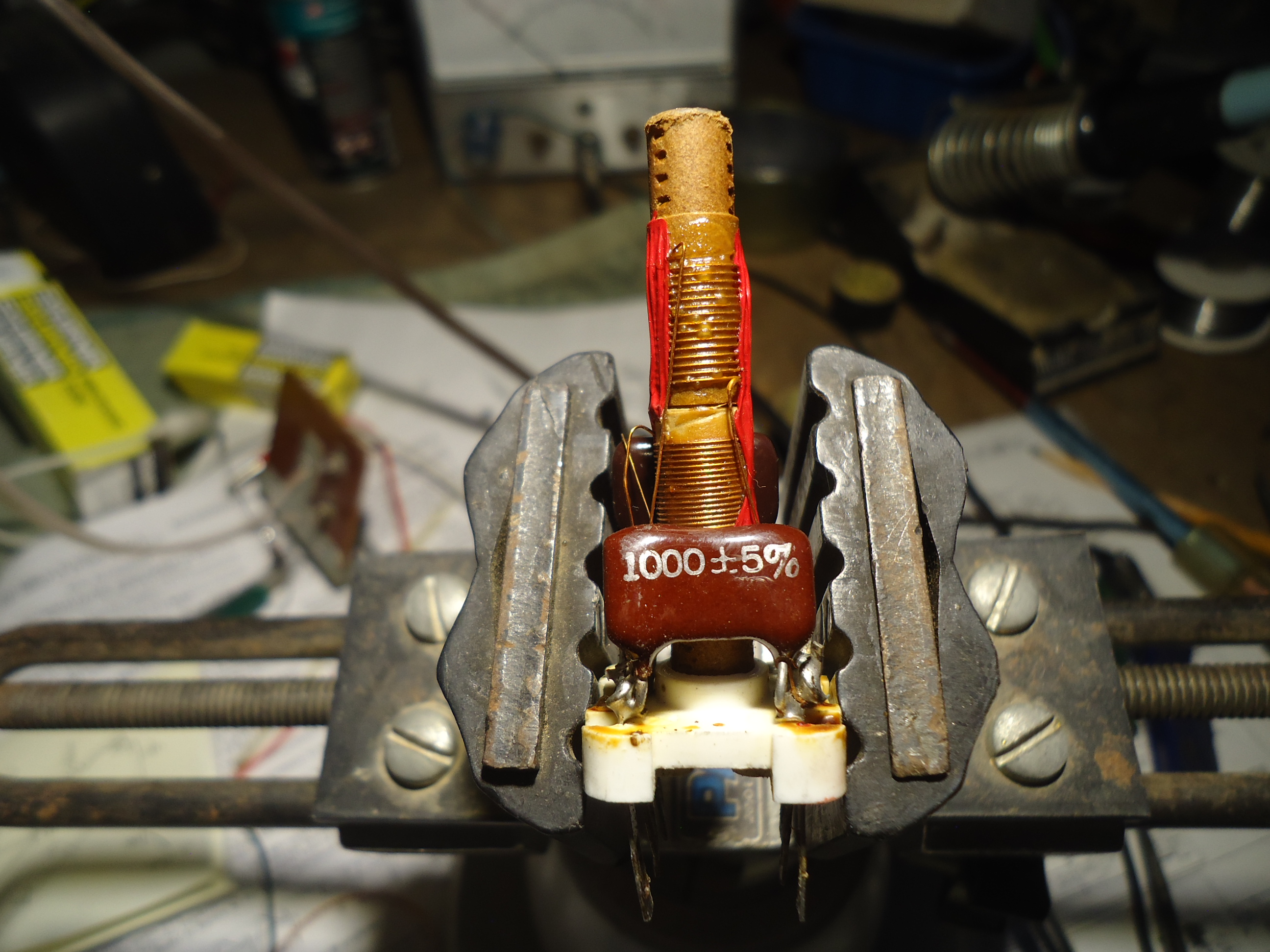
Pix 3 The other cap on the other side, a 1000 pf old cap.
Pix 4 New 5% 1000 pf cap installed
Pix 5 Bandpass XFMR re-assembled
Pix 6 The repaired ground with busswire attached.
Next, we install the XFMR and replace the 6CB6 3.58 MHZ local oscillator socket.


Update July 13, 2024
From Mike,
Good morning. The work on the CW Driver transformer is complete. The 6CB6 3.5 mhz local oscillator tube socket has also been replaced. The AFPC (hopefully final) alignment went as expected. 6 photos follow over 2 emails.
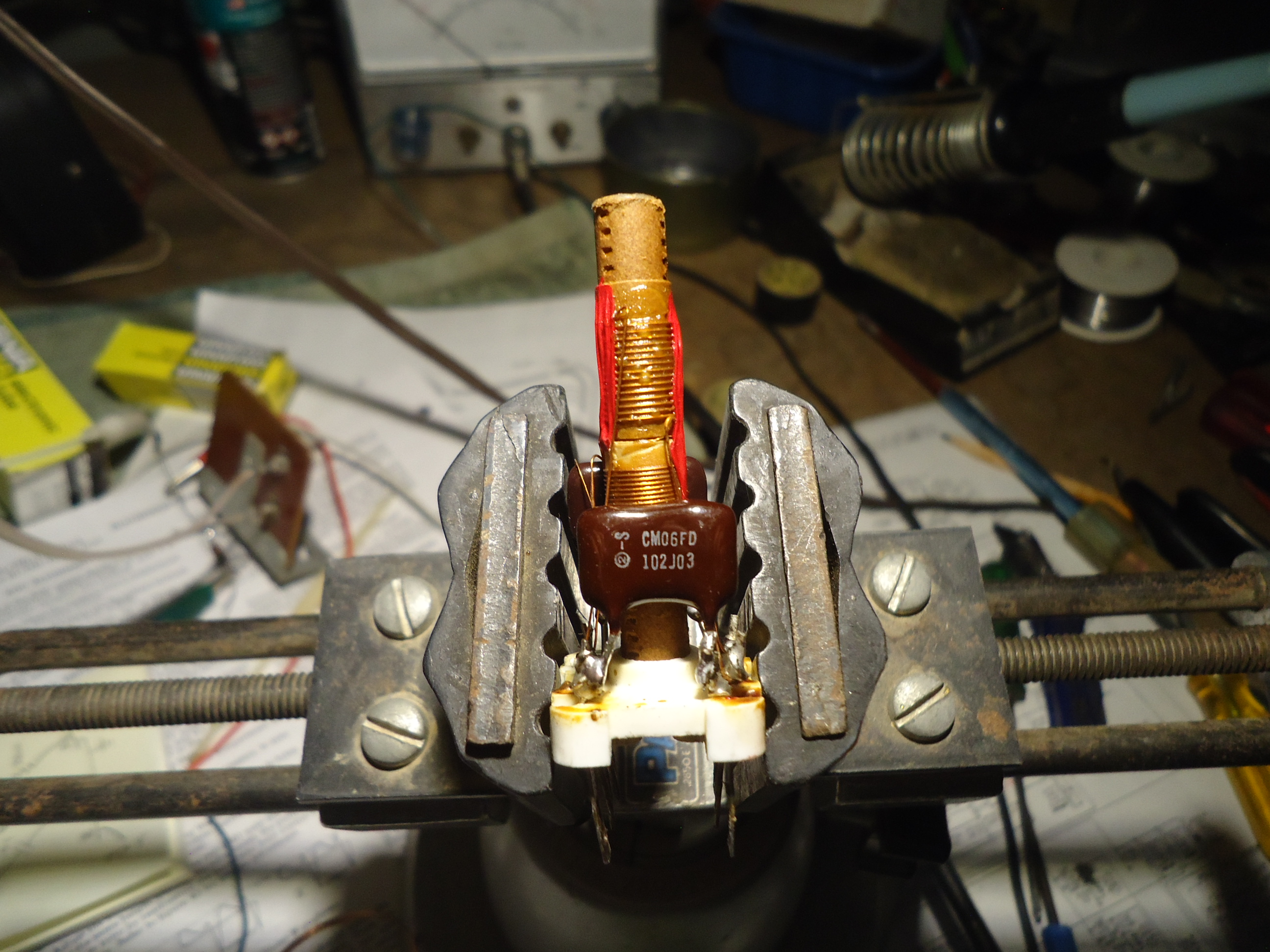
Pix 1 The CW Driver transformer with the external componects replaced. The old one had to be removed and discarded in order to disasswmble the unit for the internal capacitors replaced which was previously described.
Pix 2 The badly overheated tube soket for the 6CB6 local oscillator.
Pix 3 The socket removed.
Pix 4 New socket installed.
Pix 5 Chroma pattern after AFPC alignment.
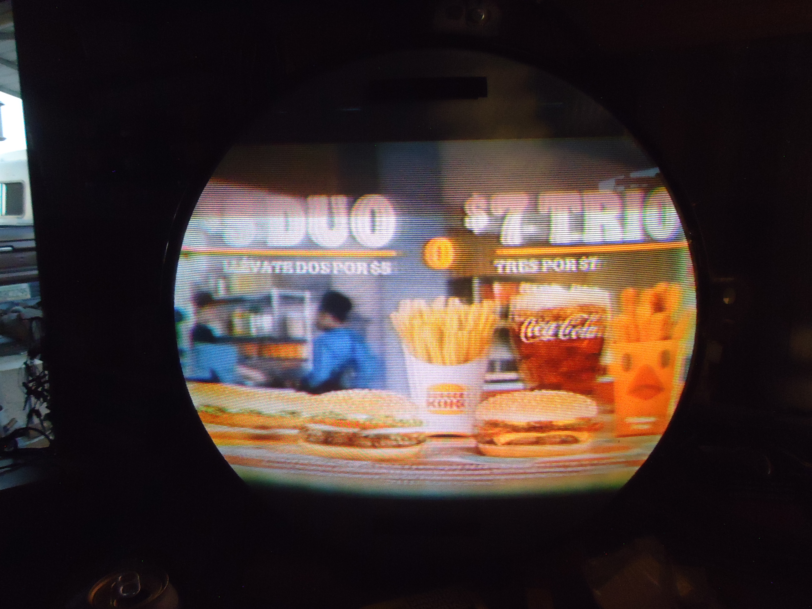
Pix 6 Real time image over the air. Best I could do.
Onward to cooking it on the bench for a few days.
Stay Tuned!!


Update July 20, 2025
The restoration by Mike Doyle was completed today with the delivery of the RCA CTC-5 Chandler Deluxe model to my residence. Watch a 3 minute video to see the results.
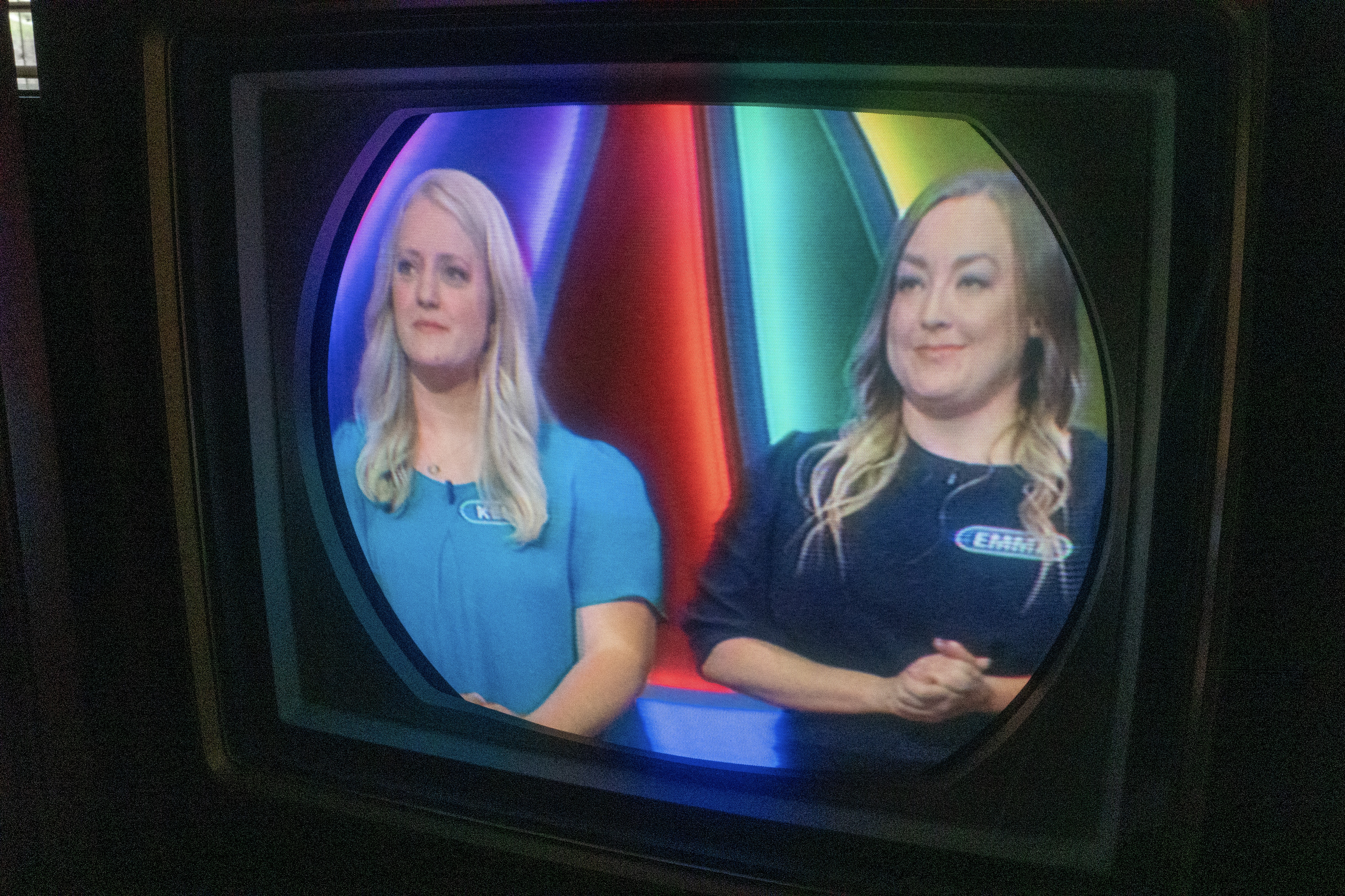
Update July 23, 2025
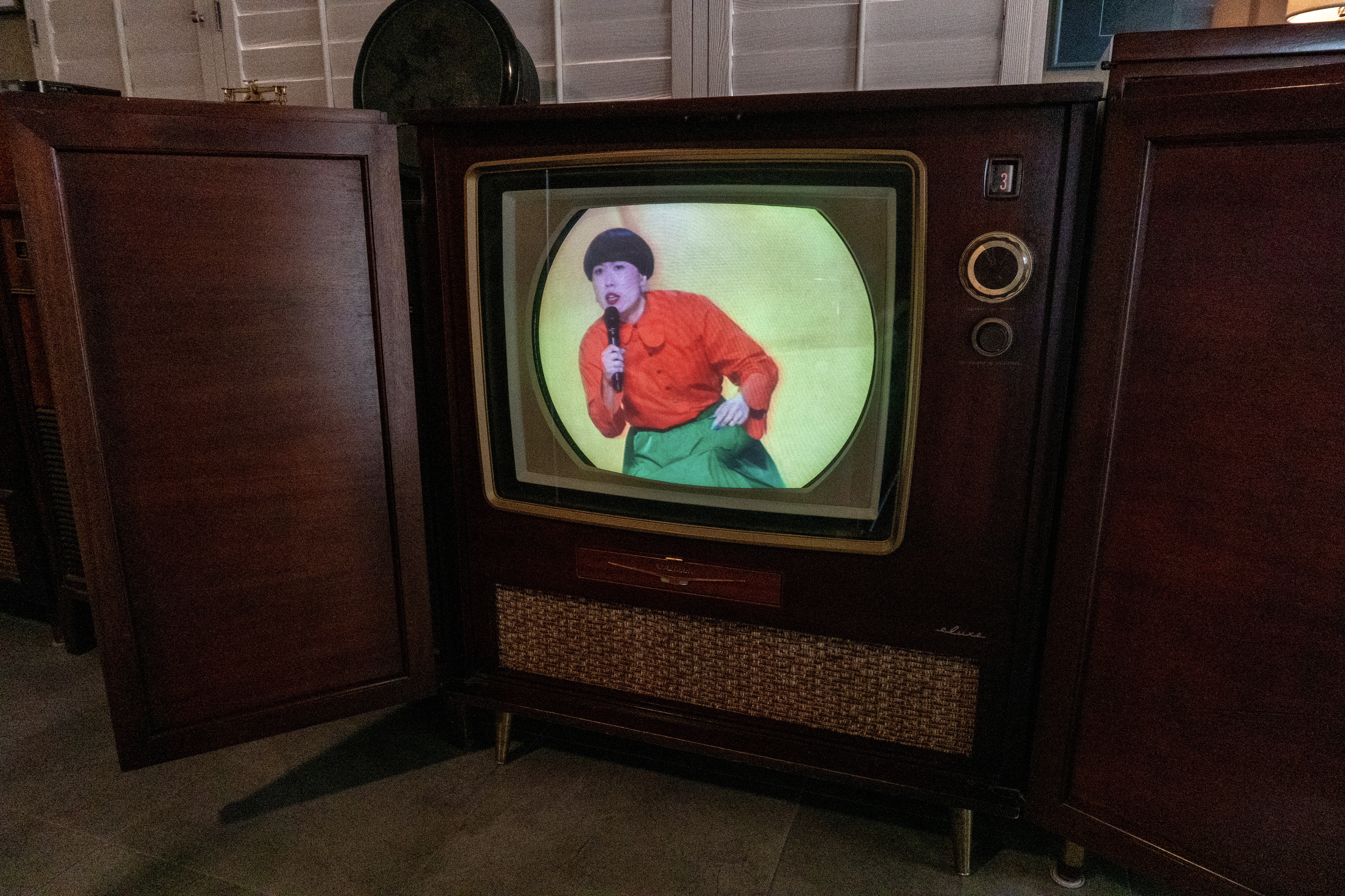
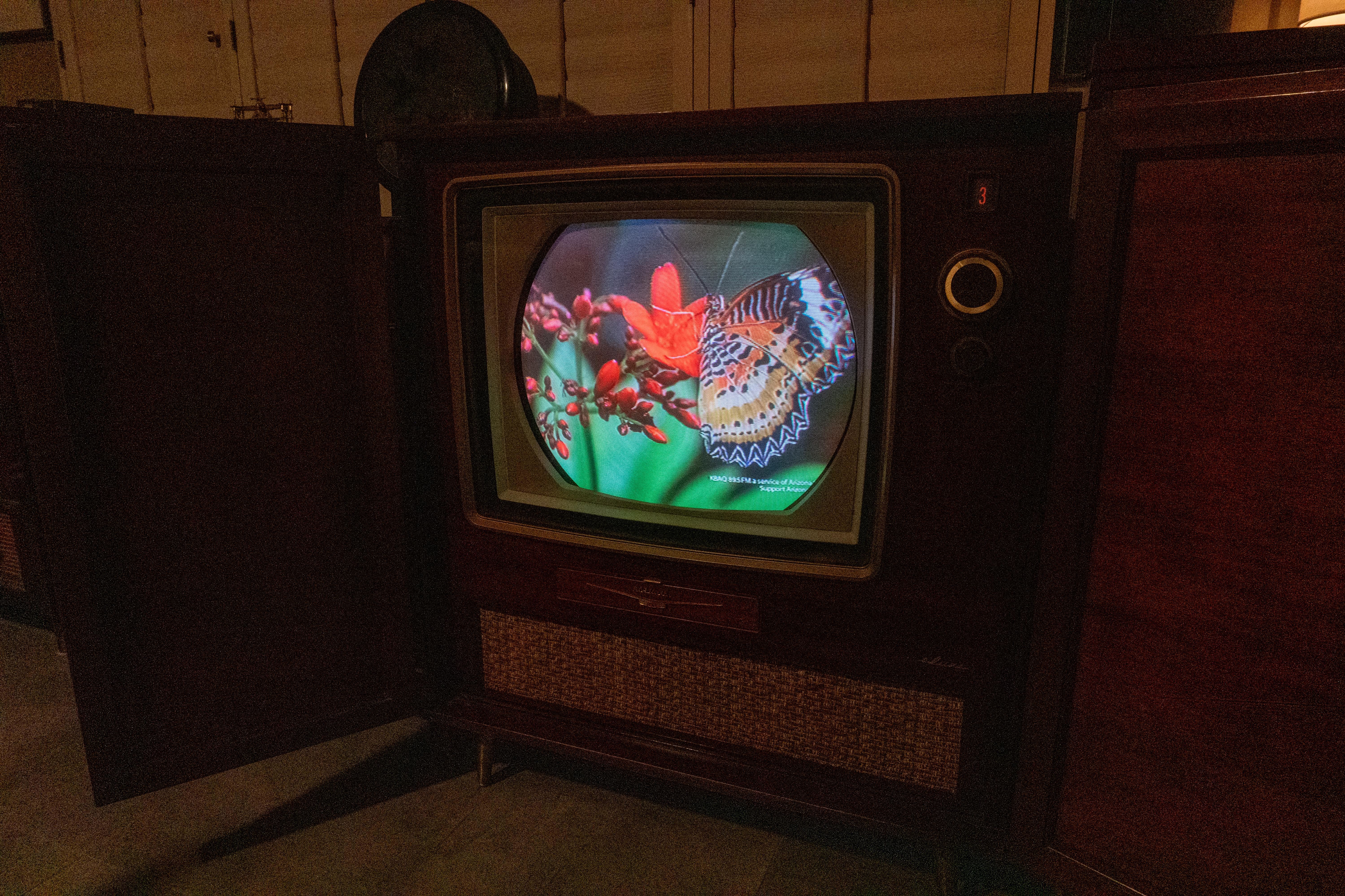
Direct view screenshots shot July 22, 2025. Tap on image to view full size.


Update, August 10, 2025
On August 3, 2025 I heard a snap sound while watching the CTC-5, but all appeared normal. The set continued to work well the next day and on August 6, 2025 about 1 minute after power up, we lost raster 100%, but we had sound. No smoke, no odor. An anxious call to Mike ensued. The following is from Mike.
Greetings Marshall. Since my return on Aug. 3rd to attempt and finally fail to do a repair there, the chassis has returned to the bench at my home. While at the house on the 3rd of Aug, a 3/10 amp flyback protection fuse was found to be blown. You reported several loud snaps prior to the loss of raster on the set. The source of those snaps is still unknown but the suspicion is that there was an arc from the top of the 6BK4 regulator tube which previously during all restoration processes, the H.V. top cover was removed and not installed until the day I returned the chassis on the 20th of July. After replacing the fuse and all of the sweep tubes, I only had weak H.V. (about a kilovolt). And the filament on the 3A3 rectifier could not be seen an illuminated. That is when I decided to return the chassis to my bench for further testing.
The first thing that I did was install solid state rectifiers in place of the 3A3 H.V. rectifier and also on the 1V2 focus rectifier. This restored the raster but not with full screen width. About 2 inches short on left and right sides. I also noticed that there was no control over the H.V. by way of the pot that I installed during the restoration. This was corrected by replacing the 6BK4 regulator tube. I now have control over the H.V. I suspect that this tube failed and caused the arcing within the cage but I will never know for sure about the sequence there. No way to know. I have done a number of tests througout the Horizontal sweep circuits and my conclusion is that the flyback has several shorted turns in the primary winding which is causing lack of full sweep and also lack of enough current to supply the filaments of the 3A3 and 1V2. All of the resistance values of the flyback are within range according the the Sams Photofact documentation but a few shorted turns of the very small wire of the primary which normally measures 450 ohms, would be impossible to detect since when the documentation was done sometime in 1956 or 57, digital meters had not yet been invented so precise resistance is only rough for us at the 450 ohms.
Since all other parts of the sweep circuit seem to be OK, I will be installing my one (and only) spare flyback sometime in the next couple of days. I hope that it is a good spare. The only way to know is to install it and see what happens. I will be monitoring flyback current when first applying power.
This is where we both say a “Hail Mary”
Cheers, Mike
Update, August 11, 2025
Greetings. The operation was a success. The patient lived. Normal H.V. 21KV (and adjustable). Full sweep and good focus. Flyback current is 220 ma. Same measurement with failed fly was 300ma. All good now. I will cook for a couple of days but for short periods and only at night with this heat.
Cheers, Mike
Update, August 13, 2025
I have cooked the chassis several more times today. All looks good. Before I changed out the transformers, I used my digital ohm meter to compare the primary transformer resistances in order to further prove that the transformer had failed. The proof was there. The failed unit was 466 ohms and the replacement unit was 491 ohms. So, there is a 25 ohm difference which means a short in the winding. I decided to open up the top of the H.V. cover with 2 big holes for ventilation. It should not compromise any safety issues with fire. After about an hour of operation in the shop with the temps at 100 degrees, the flyback was only warm to the touch. This is a very good sign. Also, the width control switch is now a minimum width instead of maximum width. It is a 3 position switch that selects different windings of the flyback for sweep width. Also a very good sign. My last evaluations of the flyback failure is not only due to the failure of the H.V. regulator tube, but more of long hours of continuous operations in hot conditions. It very likely would have failed very soon anyway. The Sams Photofact calls it out as 450 ohms. Back then, only analog meters were used for this type of documentaion. The RCA print does not call it out at all. As a point of reference here, I am including more numbers for the flyback. RCA printed what was known as the “drawing numbers” on almost every part. Those numbers are different from the actual part number. So, if we go surfing on the internet for a transformer, both numbers need to be known and displayed. Here they are:
RCA Part number is 102132
RCA Drawing number is 1106255-1
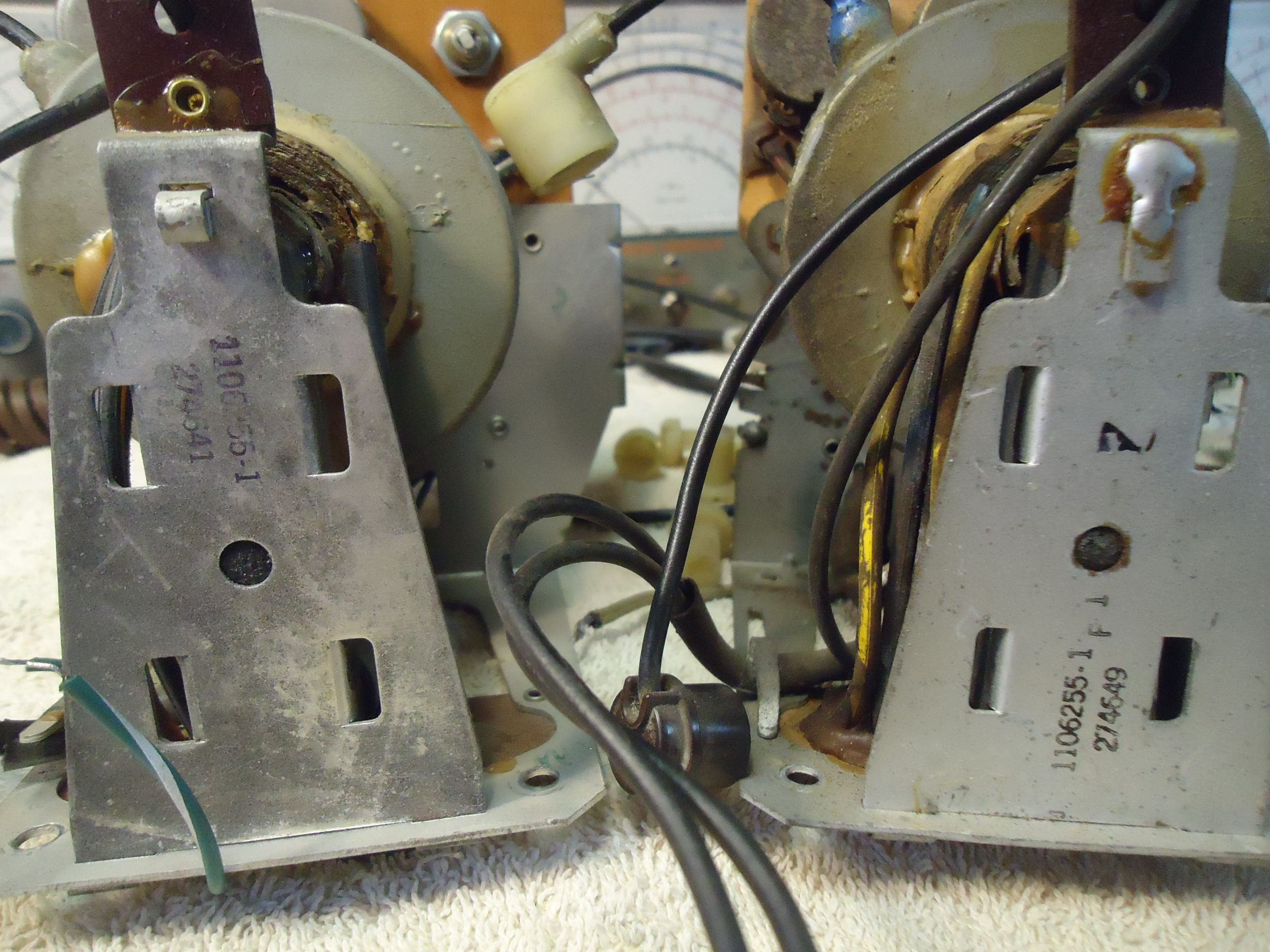
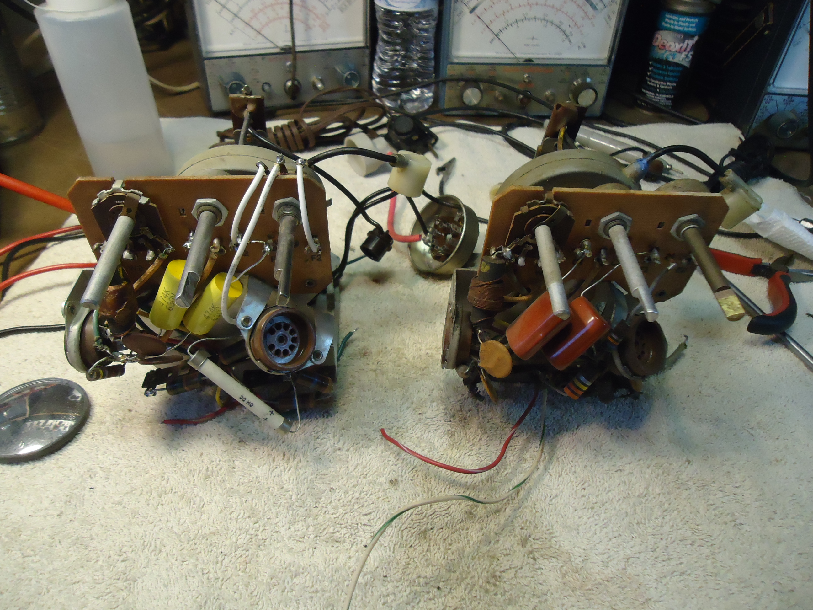
Pix 1 Failed flyback on left and repalcement on right.
Pix 2 Same with other side view.
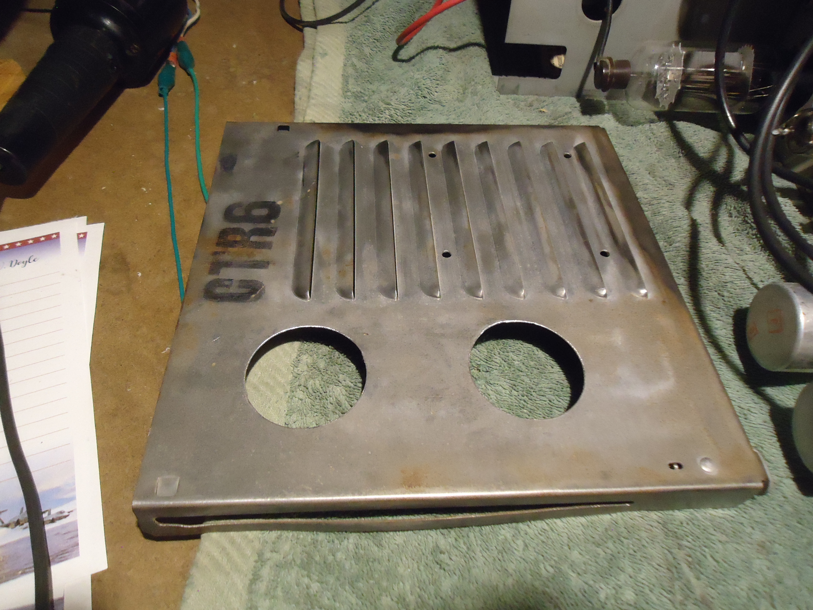
Pix 3 Modification for H.V. cover.

Update, August 17, 2025
Mike came to the rescue and returned the CTC-5 chassis with a replacement flyback transformer from his donor chassis and all is well. The contrast is better with the new flyback and Mike noted that the horizontal sweep control is set at minimum range which is an indicator of a stronger flyback. He said the old flyback that failed, had the sweep set to maximum to sweep the horizontal raster.
One week later, August 24, 2025.
New screenshots and a video clip from Wizard of Oz. We compensated Mike well for the restoration and I’m grateful for his generous donation of his personal back up flyback for his CTC-5. Now on hunt for a CTC-5 donor flyback to pay it back.
Tap on below image to watch a brief video from Wizard of Oz on the RCA CTC-5.

⏯️


Posted November 29, 2025
Happy Thanksgiving Weekend
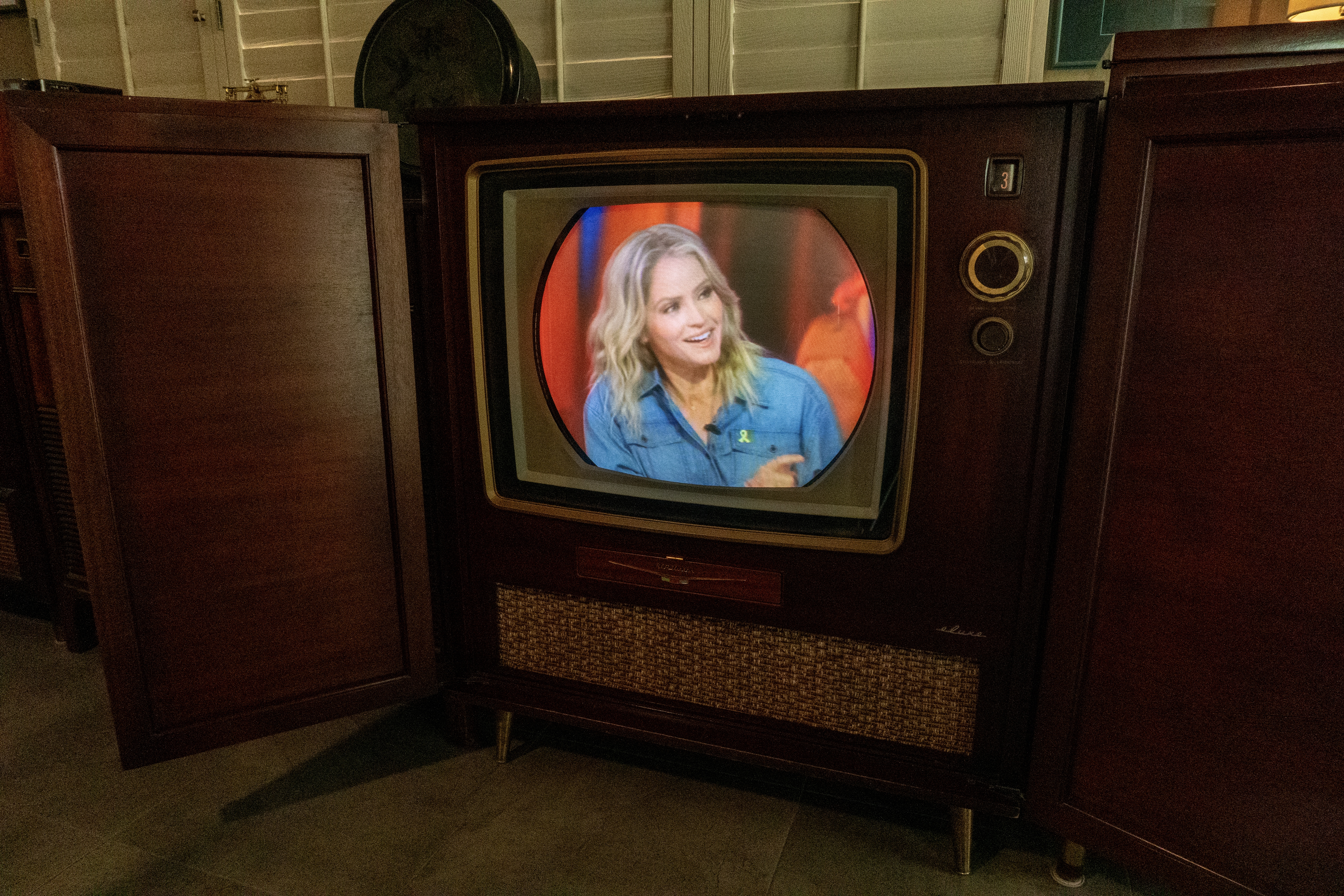
For this event, we usually post screenshots from our Westinghouse H840CK15. This year we have shots from the 99th annual Macy Thanksgiving Parade on Thursday.
Television: 1956 CTC-5 Deluxe Chandler.
Camera information: Sony A63 on tripod, shot in RAW, 24mm, 1/25 sec; auto white balance, aperture F13. Developed with Adobe Lightroom for iPad, auto Adobe color.
Stay tuned.