
Indextron

CHAPTER TEN
This page is devoted to the Beam Index color tube known as the Apple, Advanced Apple, Crab Apple, Uniray, Zebra, Lollipop, SanFlat and Indextron. I will dispense with the early development by the Philco Corporation and others in the 1950’s and succeeding years for now. There are good references on the internet. Click on below image to read PDF.

Courtesy Radio History

Shown is one of many prototype beam index televisions developed by Philco starting in the latter portion of 1949. By the time this magazine hit the news stands, Philico had nearly given up on further development of the beam index color CRT, code named “Apple”.
If you have the patience to read through the transcript of this court case, RCA vs Philco et al, toward the end of testimony and the many Philco internal memorandums, you will see how Philco struggled with the Apple tube and stopped development at the end of 1957.
Posted January 27, 2023
Recently we re-read the RCA VS PHILCO court case, Re: Apple Tube. Philco built many prototype CRT’s and each had unsatisfactory results. The tech notes from the engineers: too hazy, fringe, rosey cast, green cast, bullseye, etc., and labeled unsatisfactory. As evidence, the lawyers showed photographic exhibits of screenshots of the Apple tube and an industry standard fruit bowl image used by Philco, Westinghouse, GE, RCA, Admiral and others.
I found the fruit bowl image and believe it to be a reproduction of the original NTSC color image from an unknown color CRT, but probably RCA’s image from their prototype 15GP22.

Courtesy Electronics Magazine.
The above and below cover photo shows a prototype Philco Apple with a “rosey” image of the same fruit bowl.

The following documents are from retired life long General Electric engineer, Avon C. Campbell. Thanks to John Atwood for releasing them.
An interesting antidote, General Electric Color engineering department referred to the Philco Advanced Apple as the “Crabapple”.
Click on below image to read PDF.

Posted March 16, 2023
Jerome H. forwarded two PDF technical documents from Philco describing the details and development of the Apple tube. Thank you, Jerome and just tap on images to open.
Part one

Part two

Work continued on the Philco concept into the 1970’s by one of Philco’s former engineers, David Sunstein who created a spin-off company and tried to secure funding for his Uniray CRT. A number of problems with the original prototypes were overcome and a good working prototype was achieved, but there was little interest and the project ended. We pick up on further developments starting in 1981.
1981 Sony 30 inch Beam Index Prototype
* A 30″ beam index color CRT, currently the world’s largest, employing the beam index technique for color reproduction has been developed. The tube neck is 30.6 mm in diameter and the deflection angle is 114 degrees. The screen, consisting of 485 triplet (one triplet consists of RGB trio) color phosphor stripes with a pitch size of 1.3 mm, displays a good quality picture.
With the cooperation of the Sony Research Center the efficient beam index phosphor Y3Al3Ga20l2:Ce, is employed. The phosphor has a suficiently short decay time. A new large active area PIN photo detector with an integrated amplifier provided by the Semiconductor Division is incorporated in the CRT.
The inner panel of the tube is cylindrical, as in Trinitron tubes. The three primary color and index phosphors are screened five cylindrical individual glass master mask patterns. A new method of screening the index phosphor on the aluminum film has been achieved.
The CRT employs a newly designed high resolution electron gun with an astigmatic pre-focusing lens and a large diameter magnetic focusing main lens. When this new gun is employed in this CRT, the power consumption of the beam deflection yoke can be reduced by reducing the neck size, regardless of the lens diameter chosen. As the new gun has a small spherical aberration, the beam spot width can be 15 to 20% smaller than that obtainable by a comparable electrostatic lens in a uni-potential type gun.
The tilt correction for the deflected beam spot is achieved by means of quadrupole magnetic focusing techniques. Together with a newly-designed deflection yoke, the electron gun, which has a unique elongated G3 aperture, gives an electron beam spot free from distortion over the entire CRT screen. Instead of using conventional oxide material, the cathode is made of a new iridium-coated impregnated material to ensure a long emission life.*
This CRT did not go into production, but begins Sony development of beam index technology.
Read more here.
* Below two images, Copyright Sony. Licensed to this author only.


1983-84 Hitachi Beam Index CRT
Watch the video to see it in operation.

This is the first beam index color CRT brought to the consumer market in 1983. It’s specification states a 1.5 inch diagonal measurement, but it is slightly smaller then the 1.4 inch Panasonic CT-101A color CRT. It measures 1.25 inch making it the smallest color CRT in the world made for the consumer market. In fact, this color CRT is only 1/16″ larger then the solid state LCD screen on the Seiko TV Watch. What makes the Hitachi CRT unique is that it utilizes beam index technology, producing a color image with one gun, one electron beam and no shadow mask or color selection mechanism. This CRT was first incorporated as a viewfinder in the RCA CC-30 color video camera in 1983. My CRT is part of the RCA CKC021 color video camera introduced in 1984. The viewfinder can be detached from the camera body. There is a mirror placed at an angle to reflect the light from the CRT which is placed perpendicular to the magnified eyepiece. This index beam CRT operates differently from the Sony FP-62 and the Sony KVX 370 shown below. Please read below, about the theory and operation of those beam index tubes.

Briefly, this Hitachi has 129 triplets across the screen with two different index phosphors for each triplet. One index phosphor emits green light and is mixed with the green phosphor stripe which is twice as wide as the red and blue phosphor stripes. (This may be why there appears to be an emphasis of green within the images) The second index phosphor emits ultraviolet light and is located between the red and blue phosphor stripes. The light emissions from these two index phosphors are detected by two photodiodes mounted in front of the CRT screen. The two index signals are then mixed, converted and applied to the video output circuit to drive the grid of the single gun CRT. Guardbands separate each phosphor stripe. The simplicity of this beam index color CRT, being smaller and lighter with lower power consumption requirements, allowed a color viewfinder to be used for the first time in a consumer, home brew style, color video camera.
The photos below are actual screen shot images taken from this Hitachi CRT. The images were created by focusing the RCA CKC021 camera on my Sharp 70 inch LCD television. This was done to verify operation only. Using a color video camera to capture images from a television will not provide good quality color images. This method produced under saturated color images and I expect much higher quality color images after I build a interface box to allow direct video input of any desired video source into the CRT. There are two circuit boards in the larger case and one board has color, tint and contrast controls. Adjusting these setting may yield better color rendering because I have noticed the green phosphor shows more saturated color then the red and blue. I have a circuit diagram of the 8 pin viewfinder connector and all that is needed is to hook up a few input jacks for power and video.
I’m looking into modifying the video break out box to accept an audio/video input. In doing this, we will have converted the viewfinder to become a micro television/monitor. After building the interface, I will post additional screenshots to show the results. I found this CRT February, 2014 and this CRT was manufactured June, 1984 by the Hitachi Corporation.


Tap or click on below image to see close up of pixel structure.

The diameter of the CRT funnel on this miniature 1.25 inch tube is so small, there was no room to place an index emission collection window on the outside surface of the funnel as was done with the Sony KVX 370. The solution was to mount two photodiodes in front of the CRT screen which detect the light emissions from the index stripes. One reads the green and the other, ultraviolet. The reflecting mirror, just above.


Update: July 3, 2018
Vladimir A. from Moscow sent this first photo today. Thank you. It’s a close up of a portion of the phosphor screen of the tiny Hitachi CRT. You can clearly see the low persistence ultraviolet phosphor stripes to the left of each of the red phosphor stripes. The black lines are guardbands. Vladimir also confirmed the photodiodes are identical but a yellow and purple film were placed in front of each diode. The purple diode detects the ultraviolet light emitted from the indicated phosphor stripe. The red square is 1mm on the side. I have included a phosphor layout diagram for reference courtesy Jerome H.


Update: July 4, 2018
From Vladimir.
“I gave a little photo of the “internal stuffing” to solve the question about the type of photosensors. The crystal structure and its wiring clearly indicates that the sensors are photodiodes.
In the photo the type “303” is clearly read, then the numbers “45” and “46” (obviously the week in which they were made), as well as the logo of the manufacturer – alas, although I know the logo, I do not know the name of the company.”
Authors note. The logo may be “Mitsubishi” ? It is similar, but different.


Testing the Hitachi Beam Index CRT, RCA CKC021 camera and video/audio break out box.

Screen shot from the 2014 Winter Olympics opening ceremony. Image source, RCA CKC021 camera pointed at my Sharp 70 inch LCD television. The Hitachi CRT image on the right, the reflected image on the left and the photodiode module below the reflected image collecting light from the index stripes off the CRT face. Tap or click on image for larger view.

Oversize Screen Shots below using the RCA CKC021 video camera pointed at my Sharp LCD TV as the image source.


Update March 8, 2014: Completed the interface box to allow the viewfinder to operate as a video monitor. It was easy to build, only requiring a generic 12 Volt, 2 Amp power supply, an RCA video jack, a jack for the power supply, a 10K pot, a 1/2 watt 75 ohm resister and a plastic box to hold everything. I want to thank J. Halphen for the circuit diagrams, John Folsom for the spare RCA video camera. I hijacked the Hirose CN 508 8 pin video socket from this camera. Also want to thank jr_tech from Videokarma forums for his help with the pin arrangement. The pot is used to adjust the video level. With direct video input, the color images are excellent and very well saturated. There is no longer a green color shift. The resolution looks excellent on this tiny 1.25 inch screen and the below screen shots do not do justice to the actual images. The images were hard to capture on such a small screen and they are shown 2.5 times larger then actual size.

Oversize screen shot using the video output from my interface box. The image is reversed on the CRT face, but corrected by the mirror which reflects the image through the magnifying lens in the eye piece. In testing this CRT, when we removed the plastic shell surrounding the CRT and exposed the photo diodes to normal daytime ambient light, the image and color were unaffected and operated normally. I shielded one of the two photo diodes and the image lost sync. When I shielded both photo diodes, the image lost color but was stable. When the obstruction was removed, the image returned to normal. We are trying to understand which diodes reads the UV and green index emissions.

These screen shots below were created by imputing an over the air digital signal into an NTSC analogue converter box, then passing that signal through my interface box using the video input.


The below 4 screen shots shown actual size on an iPad in landscape mode.

Below is the view through the viewfinder with the magnifying lens popped up showing the reflected image on the optical grade quality mirror. The actual CRT can be seen on the right. Cropping down this image to fit the 525 pixel wide format I have chosen for all photos on this website, reduces the resolution and detail. To illustrate the incredible miniaturization and detail of this CRT, tap or click on the image. This full size image in portrait mode on an iPad Air Retina display measures 1.5 inches, slightly larger than it’s actual size of 1.25 inches.

In summary, this Hitachi CRT was the first viable, working, consumer based beam index tube to be marketed. All previous attempts to market this type of tube dating back to the 1950’s, failed. Philco paved the way but lack of funding and interest stalled the development. The project would not go forward until the difficult signal processing could be worked out. In my opinion, a brilliant piece of engineering, a technical curiosity. If only the index beam CRT’s could have been scaled up to larger screens. It would have been possible, but new emerging technology was on the horizon. Read more below.
Next, see the first attempt to scale up the size of the beam index tube and later, a 3.7 inch beam index tube and a 5.25 inch beam index tube.
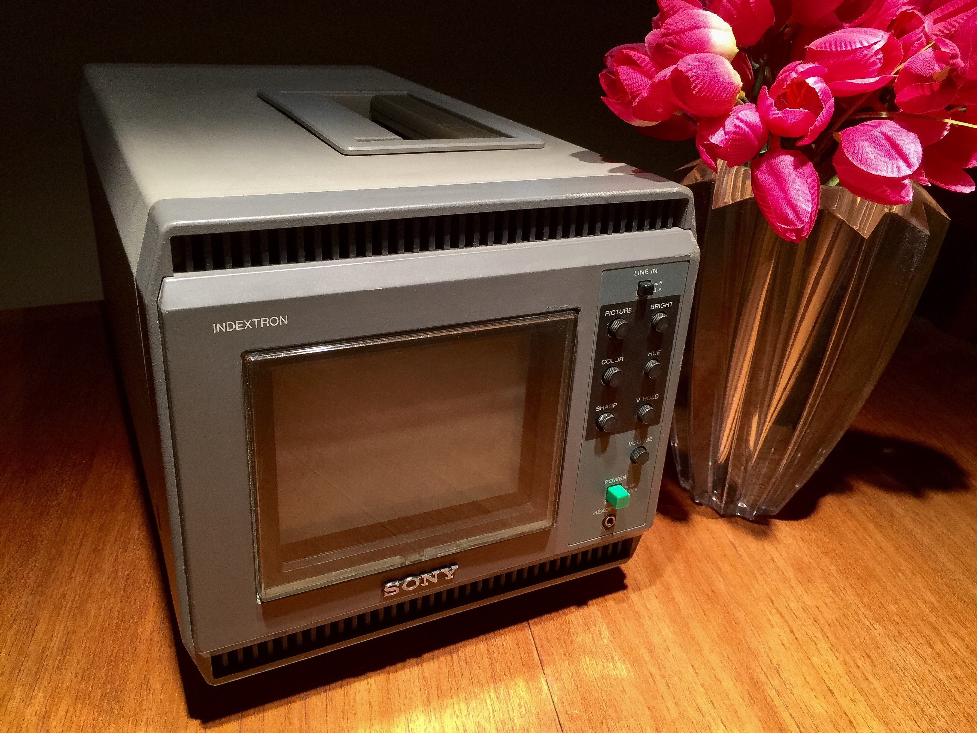
1984/1985 Sony Vidimagic FP-62 Indextron projector
This was Sony’s first Indextron product, the Sony FP-62 (along with the FP-60) portable projection television. Sony’s promotional material stated this was the first one tube, one lens projector. The projected picture is created using a single beam index CRT, together with an adjustable lens assembly. The greatest virtue of the system is that the alignment of the three primary colors of light, red, green and blue, are not affected by distance and convergence requirements. Alignment is not critical as it is with the common three tube units. The single adjustable lens allows the FP-62 to be transported and set up without system alignment. A test signal, with cross hair image, is incorporated for fast, easy focusing by use of a touch sensitive control panel, operating like a common slide projector. Any bright surface, but preferably a screen with gain, can be used for imaging, as long as the unit is placed between 3 to 9.7 feet away (30 to 100 inches). Diagonal size of the picture area displayed can be adjusted from 30 to 200 inches. Picture brightness is 50 foot-lumins with a 55 inch projected image, but apparent brightness drops off with larger images. The projection tube is a high brightness 5.25 inch, one gun, one lens, one beam, without shadow mask, index beam color CRT, sealed in coolant, ethylene glycol-water, claimed to have a peak brightness of about 1600 lumen. In this design, the vertical, parallel color phosphor strips are laid down much like the Sony Trinitron CRT. The index strips are laid down behind the red phosphor strips and the single beam (writing beam) converges at the deflection center so that single magnetic deflection and focus is all that is required. The reflected ultraviolet light from the index phosphors provides a feedback signal detected by a photo cell. This signal is used to index the position of the writing beam very accurately. The focus is electro-mechanical, utilizing a motorized system to move optical plastic elements sealed inside the unit. A tuner is incorporated to receive UHF, VHF and cable channels 1-125, allowing the unit to be used as a standard projection television. Video and audio inputs are provided to allow external sources to connect. An enclosed speaker is provided or external speakers can be connected. An accessory microphone/wired remote for voice-over audio was available. The picture it produces is sharp and the large size over a short throw distance is impressive. Works best in low-light surroundings, remembering this was 1980’s technology. It was originally designed for non consumer, professional use. The light, portable, fast and easy set up, made it ideal for video/audio presentations in the board room, sales and demonstration purposes. Just plug it in, connect to a video source and play. (The Model FP-60 had a built in Betamax video tape recorder.) The Sony FP-62 originally retailed for $2195.00 U.S. dollars and this model was manufactured January, 1985. Thanks go out to MisterBetamax for research material.
It came complete with audio/video cables and travel satchel with storage compartments. It has a carrying handle and an adjustable stand to adjust height. A flip down, hard cover protects the projection lens in transport. This unit is missing it’s hinged, plastic control cover, however subsequent to the below photos, I found a control cover from another source. It pops right in. (April 25, 2011) The unit measures 9 1/8″ W x 11 3/8″ H x 26 1/2″ D and weighs 29.5 lbs. I purchased this set, March, 2011.
The Sony FP-62 arrived safely today, March, 17, 2011. The screen shot photo shown below, is right out the box, photographed in less then ideal conditions. Plugged the power cord in, attached a digital converter box, placed the projector on it’s end on the floor, pointed it up at the 8 foot 1 inch flat white ceiling. ( I do not have a single white wall in the house, that’s why the ceiling 😉 ) No attempt was made at this time to adjust focus, color, tint, contrast and brightness controls, just straight out the box. Photographed in mid afternoon, with blinds closed. There is light leakage from a window on the left. The picture is about 60 inches with a throw distance of six feet in this shot.


Here is the the same image, same size, but now in a dark room, with the focus and picture controls adjusted. Still projected onto the flat white ceiling, looks much better. The image has perfect convergence, with very little keystone effect, over scan is moderate and the image is bright, remembering this is 80’s technology. I owned an Advent three tube (CRT) 750 and a Kloss NovaBeam three tube Model 1-A from 1977 and 1984. Although these projectors were brighter, the performance of this Sony is better. The one gun, one beam, without shadow mask, beam index tube is the key, producing very bright light because there is no shadow mask blocking the light. One tube, no convergence problem. I remember the Advent and Kloss constantly drifting out of convergence during warm up. They took several hours to lock in, during this time, constant adjustments of the built in cross hatch generator patterns were required. No such problem with this Sony. Compared to today’s current projectors, the image is best described as dim with soft focus, but never the less, an interesting technology to play with, still very viewable and excellent for it’s time of introduction. All controls are functioning including the motorized focus control, with a back up manual focus adjustment. The images from this Sony would really pop with a proper screen.

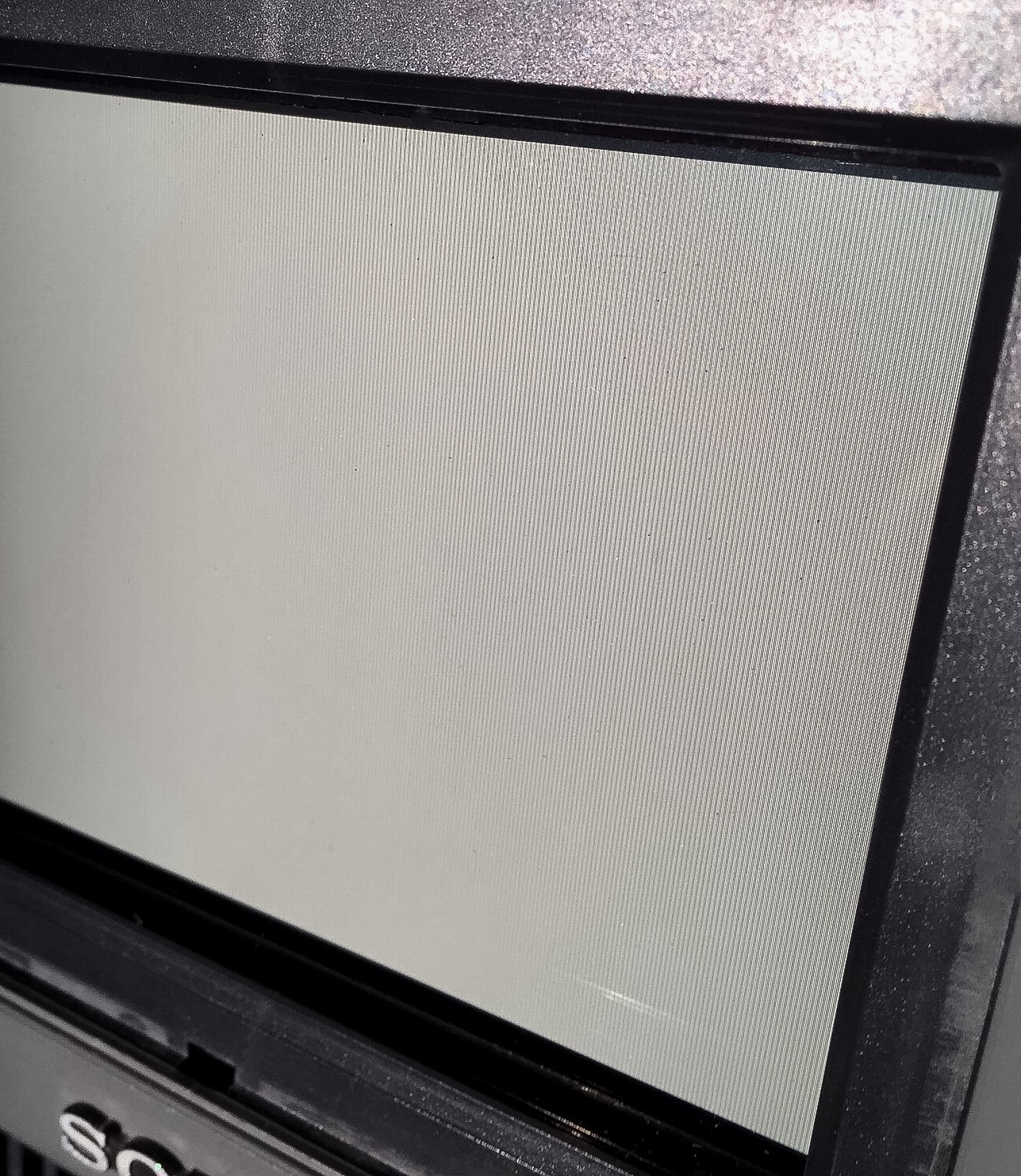
A few more screen shots, all taken the same day, approximately 60 inches diagonally, on a flat white ceiling. The phosphor strips, are not as visible as on the Sony KVX 370 Indextron, direct view television described below. This next screen shot can also be seen on two LCD televisions on page Three-A


A close up of the phosphor strips.


Update October 12, 2023
Tap on below image to open PDF, courtesy BM/E.

After acquiring a proper screen, I will post additional screen shots.
UPDATE, FEBRUARY 24, 2020
We recently acquired a second Sony FD-62 for the purposes of tear down. Since the set is fully operational, we only removed the cover and prepared this video.
Still shots from the video. Tap any image to open full resolution. Note: Correction to my narrative. Introduction year was 1985, not 1987.


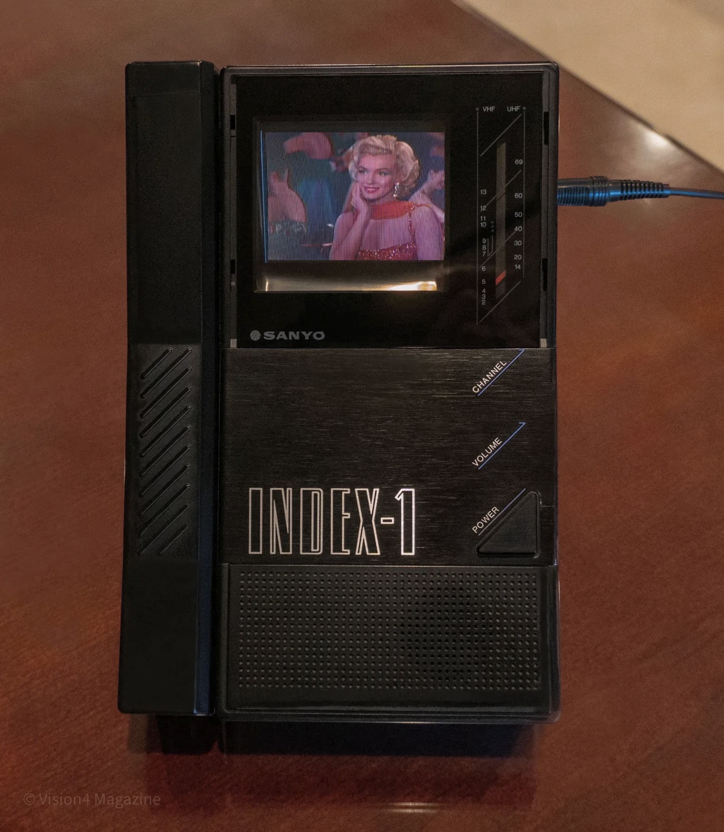
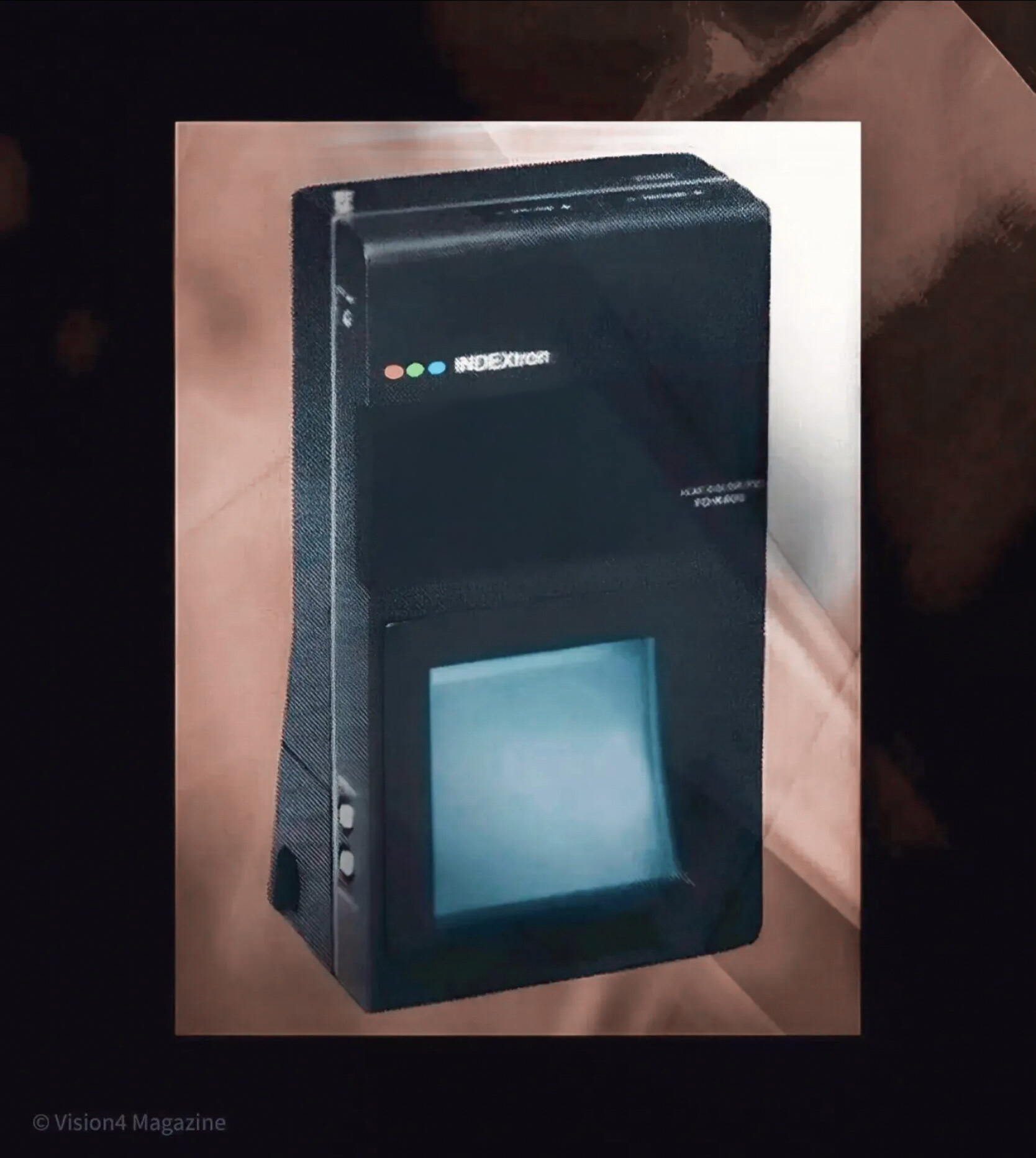
SANYO SANFLAT
Prototype Sanyo Beam Index and Index 1 production ready Beam Index Television
1985/1986
In June, 1985, I picked up the latest issue of Popular Science magazine as I had done many times before.

In that magazine, we found an interesting article about a new color television which used a flat color CRT, much like the Sony monochrome Watchman’s introduced a few years earlier. Of course, at that time it was cutting edge technology! and I was eager to learn more.
The article went on to describe the set was being shown for the first time at an international exposition in Japan. Sanyo of Japan demonstrated in Tsukuba, Japan, a 3 inch color prototype Beam Index tube nicknamed “Lollipop” because the display broadened out above the tubes gun, much like Sony’s flat black and white CRT, first introduced in 1982, called the Watchman model FD 210 and shown on PAGE TWO of this website.


When I first saw photos and read about the prototype back in 1985, I could not wait to purchase. If you have one and would like to sell it, please contact me.

Sanyo 3 inch Beam Index Color CRT courtesy Sanyo Corp.


Additional specifications: 3 inch color 60×45 mm. Brightness 200 nit (Sony KVX 370 200 nit) Black Level 6 nit, Resolution 125 TV Lines (Sony KVX 370 150 TV lines) Contrast ratio 33:1 (Sony KVX 370 more than 50:1) Three index stripes for every four color triplets, 145 total triplets (Sony KVX 370 148 triplets) Dimensions 122x235x50mm, CRT 42mm thick, Deflection angle 47 Horizontal, 16 Vertical, 5 watts 12 volts DC, 100 volts AC.
The below 3 inch color Sanyo SanFlat shown may have been marketed in Japan for a brief period.
COVER STORY


POSTED OCTOBER 31, 2010, Production ready for consumer market?

Sanyo Index 1 Courtesy Sanyo, J. Halphen and David
Were there others? Finding a real Sanyo Index Beam television would be the holy grail for collectors.
POSTED JANUARY 19, 2022
WORLD’S FIRST AND ONLY FLAT COLOR CRT TELEVISION
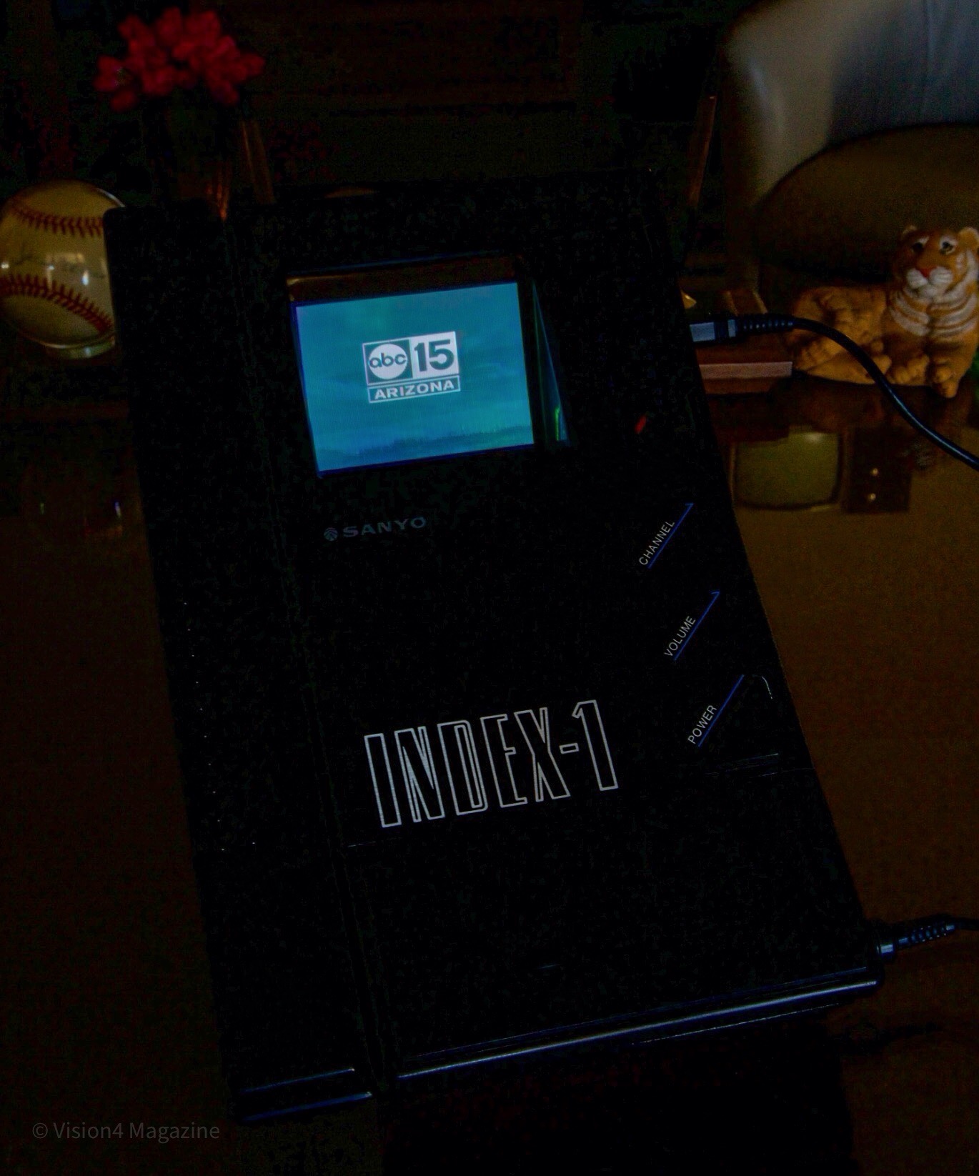
1985 Sanyo 30CTV1
We found one and as a collector, I’m ecstatic! The impossible became reality. VideoKarma member Jerome H., found the first picture in 2010 and back then, I had doubts it was ever manufactured, but here it is! This television is the first and only FLAT beam index color CRT made available to the public. Sony made a prototype, but never released to the best of my knowledge. Introduced in 1985, the Sanyo predates the well known Sony KVX-370. We became aware of this set in 1985 from published articles in Popular Science and other magazines and have been searching diligently the past 12 years after my career retirement.
This set uses the “lollipop” style CRT, with screen being 3 inches diagonal and 42mm at its thickest point. Deflection is 47 degrees horizontal, 16 degrees vertical. The set has all the usual controls and inputs including AUTO COLOR and AFT. A detachable battery pack holds 8 double A batteries or Sanyo’s proprietary rechargeable batteries. The set measures 9 H X 4.5 W X 1.75 inches thick with battery back detached. I have the 12 volt power supply and leather case with the find, but no paperwork. We now know at least 102 sets were manufactured based on the serial number.
The set is in very good condition, just needed cabinet cleaning. The front viewing screen is glass, not plastic. An adjustable stand is recessed into the rear cabinet and the antenna is straight as it should be. The set feels like 2.5 pounds, a guess. Jerome was correct, the set appears to be for American standards and the label on the back reads “Assembled in U.S.A. with Japanese components.” How often or odd is that.
Indeed, after cleaning we attached a digital converter box, set the dial to channel 3 and switched on the power hoping for the best and behold, we had a gorgeous lollipop, indexed color picture! The color and brightness looks comparable to the Sony KVX-370, but the RGB stripes have a finer pitch, so the images appear in higher resolution.
In the simplest terms, a black carbon material is laid down under the 145 triplets for better contrast and every 4 RGB stripes are sandwiched by non emissive index stripes that emit something close to ultraviolet light which is collected by a light collector plate attached at the rear of the CRT. A diode attached to the top of the plate send the UV light to a custom IC processor that indexes the single electron beam to the proper RGB phosphor stripe. No shadow mask or aperture grill. In this scheme, the electron spot size is critical so it won’t spill over to adjacent phosphor stripes and contaminate the color.
In a few screenshots provided below, you can see the index stripes above and below the RGB stripes and gives you an idea of the spacing between them. A single strange lit blue stripe can be seen at the left and end of the run in field. I’m not sure of its function.


Battery compartment detached.


Copyright top three images below licensed to author only by IEEE.


Here we see a Sony A6300 recording a video from the Sanyo Index-1. The Index-1 screen is badly overexposed.


1986 SANYO WALLVISION
Prototype or market ready product? Sanyo expressed the desire to produce new products using their newly invented SanFlat beam index color CRT. This appears to be a working model of what might be considered a video doorbell communication device, but it is also equipped with a television tuner. You can see the volume up and down, channel up and down and color adjustment control with digital display. In this design, the 3 inch color SanFlat CRT was flipped upside down, Sony 4 inch Watchman style. It’s called WALLVISION.

1987 SANYO VIDEO PHONE.

NEXT, MORE INDEXTRONS BY SONY.
At about the same time, Sony Corporation was developing a very similar, color beam index flat CRT. This is evident by the design drawings in their U. S. Patent filed September 12, 1986 and issued July 12, 1988. Figure 1

At the 1987 International Paris Air Show, Sony and Sunstrand Data Control developed and demonstrated an in flight entertainment system, incorporating this four inch flat color CRT designed to be built into the back seats of commercial aircraft. We are still trying to find photographic evidence of this CRT.
Posted December 29, 2015
At last, the first known photo of the prototype 4 inch flat color Watchman surfaces! Very similar in style and execution to the 4 inch black and white Watchman’s. Was this set sold for a period of time? To prove image stability in a portable color television device, Sony tested this prototype’s servo circuits and exposed the set to terrestrial magnetism typically found in North America with excellent results. This indicates the set was intended to be marketed in the United States. We hope to find one and it would be the holy grail of all finds.
Specifications
Screen size: 4 inches
Luiminance: 200 nit
Contrast ratio: More then 50
Resolution: 150 TV lines
HV: 8 kV
Power consumption: 0.8 W (6.0 V DC)
The screen is arranged with three index stripes per two triplets with a total of 168 triplets. A triplet is one set of RGB stripes. The index stripes are set 0.32 mm apart. The short persistence P47 index stripes which emit UV light are separated from the RGB stripes by a thin aluminum plate for increased purity and high s/n ratio. The condenser plate which collects the UV light, essentially backs the entire flat florescent phosphor screen and two photo detectors modules are mounted at the top edge of the condenser plate. The spot size from the new gun aperture has been reduced to one half the spot size of the 4 inch black and white flat CRT Watchman. In order to keep the prototype receiver compact, the index signal processing circuit is packed with three newly developed IC’s. (Apparently the same three IC’s used in the KVX 370 reviewd below) The CRT measures 215L X 109.2W X 36.7D mm. The screen size is 80.8W X 61.0H mm. The maximum deflection angle is 57 degrees on the horizontal plane and 14 degrees on the vertical plane.
Based on these specifications, the color image would be similar in performance to the below reviewed Sony KVX 370 Watchcube.
Sony prototype flat color Watchman 1986, courtesy Sony Corporation.
Watch the video clip. Copyright ©️ Vision4 Magazine


Update December 12, 2014: WHAT IS THIS?
We found a technical paper written in the Japanese language published by The Journal of the Institute of Television Engineers of Japan. Here is a photo taken from that paper.

All I could decipher was that the tube was 8 inches, was 50 mm thick and had a vertical resolution of 450 lines with 300 lines of horizontal resolution. Minimum spot size 0.4mm, 12 volt, 65ma, 10KV. The publication was dated 1968? Was this a Sony CRT or something else? Because of the year 1968, this may be an early prototype of a black and white CRT. If color, it would most likely be an index beam CRT. Here is a direct quote from a Sony press release I have on file: “Sony has been involved in the development of beam index CRTs since the chromatron era and has started serious commercialization since the 1970s”. If this is accurate, it is very possible that we are looking at a prototype 8 inch Indextron. The Google translation is very poor, but the name Sony was mentioned in the article.
A google search provided this interesting listing from PacParts,Inc.: Color Watchman Indextron CHECK STOCK $16.80 Manufacturer: Sony Part Number: CTV171189 MSRP: $17.64 A typo in the advertisement or did Sony actually manufacture a color flat screen Indextron? Would love to find one if they did.
Sony also stated during this time period that they were developing ” large, color, flat, CRT’s.” We know Sony filed a patent in 1981 for a 30 inch beam index CRT television. Have you seen these televisions? Did they actually make it to market? I encourage viewers to leave feedback. I monitor the site frequently and your comments will be posted. Created as a sounding board for interested enthusiasts, send your information, show us your Index equipment and photos. Relevant information will be posted on this page. Together we can hopefully track down these television models and all things related.
POSTED NOVEMBER 19, 2015
1987
SONY IDX-5000 INDEXTRON COLOR MONITOR.
First impressions. It looks stark, not particularly attractive. The cabinet is constructed of heavy gage metal and durable. It’s built like a vault around a small 5.25 inch CRT. Vastly superior resolution compared to the Sony KVX 370 Watch Cube Indextron shown next, with incredibly bright images. The phosphor and index stripes are much finer and closely spaced together. The image resolution and look of the CRT face is similar to a Sony KV-5300 five inch Trintron but about 5 times brighter and the black level is better. A quick analyis since acquiring the set on November 19, 2015, we set the controls to our personal preference and when the scene shifts to a pure white background, it actually hurt my eyes from the brightness. Sony says this CRT is 10 times brighter than a conventional one and I believe it. I was surprised to see a liquid bubble in front of the CRT face when we tilted the cabinet to check it out. The Indextron CRT has a liquid cooling cell attached to the faceplate, I think it’s a ethylene glycol-water mixture. An internal fan can be heard. Amazingly, after two hours of operation, the cabinet is cool to the touch and no heat is detected from the front vents seen in the below photos. The IDX-5000 has a 5.25 inch CRT.
I have been looking for this set for six years. It is extremely rare and we have never seen a photograph, let alone the actual unit. I found the service manual in November, 2010 and after extensive searching, never found anything else until now. The serial number tag on the back of the set is 17, an early production unit. I don’t think many of these sets came off the line. The set is very heavy, weighing over 24 lb, with a durable metal cabinet. The plastic screen cover can be removed for cleaning. When powering up, the audio comes up instantly, followed by the fan, then a bright white screen and 9 seconds later a beautiful, colorful, indexed image appears. The first time I saw it, the brightness overwhelmed me. The imaging is excellent. The factory states the color temperature is set at 6500 kelvin, but I have not verified this. All the rotary controls on the front of the set are push buttons. The user pushes in to adjust and they pop out. After adjustment, the buttons push in to lock. There are two video/audio line in and outs with BNC connectors, an RCA A/V input and a DC out. We read that the CRT produces 4800 nit peak white. I have not been exposed to professional color monitors, but this CRT produces the brightest light from a CRT I have ever seen. We believe Sony designed this monitor to work well in bright outdoor environments. Having no shadow mask or arpeture grill blocking the electrons from striking the phosphors explains the brightness and amazingly with just one electron beam. We believe the beam is driven harder then the consumer KVX-370 Indextron. This same basic CRT is used in the Sony Vidimagic Indextron FP-62 one tube projector shown above. Information on the IDX-5000 is limited, we don’t know much more.


Tap or click on image for full view.

These two diagrams were taken from the IDX-5000 service manual, courtesy Sony Corporation. The IDX-5000 uses two photodiode collectors to collect the index light from within the funnel. You can see the liquid cooled cell with heat sinks attached to the face of the CRT. The IDX-5000 has 13 circuit boards.


This is the Sony EM-7 Indextron 5.25 inch CRT used in IDX-5000. It is the same CRT used in the above Sony FP-62 projection television. The photo is from inside the FP-62.


Update, July 6, 2018
Tear down of a Sony EM-7 Indextron used in the Sony IDX-5000 and FP-62. Photos courtesy of Vladimir A. from Moscow. The red square is 1mm on all sides. Notice the chip wired to the photodiodes.


First screenshots from the Sony IDX-5000, all photographed November 20, 2015. (Deleted) If you have an iPad Air and double tap in portrait view the images will be actual size, 5.25 inches. It is particularly difficult to capture a beam index screenshot as the single electron beam sweeps the CRT face. It’s almost like capturing a field sequential image. Sometimes the images show just one color or look dark. My camera does not sinc well with the beam scan, and it’s unique to this Indextron. The protective plastic screen cover has a few scratches and smudges and obscures the images which are visible in these images. The cover is removable and we can rub out the scratches to get pristine clear images. Notice the perfect purity of the one beam, indexed CRT. Sony created an engineering marvel with this set, an indexed, single beam, one gun CRT requiring no shadow mask or selection device. As a result, the set achieves perfect purity, no convergence requirements and has the brightest images I’ve ever seen. Just to say it again, we acquired this set five years after first finding the Sony Watch Cube KVX 370 Indextron reviewed below. The pixel structure is much finer, with higher resolution, and increased contrast compared to the KVX 370.
Improved black levels/contrast.


These photos were shot March 4 and 6, 2020. Perfect color uniformity, convergence. No color bleed.


The index stripes are not distinguishable from the RGB stripes. By comparison, if you view the screenshots from the Sony KVX-370 shown below, the pixel structure is much courser and you can see the index stripes.
Close up of the Sony IDX-5000 CRT face with the plastic screen cover removed. You can see the pixel structure is finer then the Sony KVX 370. Tap or click on image for enlarged view.
SONY IDX-5000 SERVICE MANUAL Here is an original 65 page service manual for the Sony IDX-5000 Indextron professional color monitor, printed January, 1987, courtesy Sony Coropation. Two color circuit board diagrams, parts list, exploded views, etc. 5 1/4 inch or 133.6 mm CRT. 8 3/4″ W x 8 5/8″ H x 15 3/4″ D. Weighs 24 lbs 4 0z. NTSC. You can see the resolution was increased to 220 lines. Sony also made a IDX-7000 monitor. Drop me a line if you would like a copy.

UPDATE, AUGUST 18, 2022
I made a screen grab from a video found on YOUTUBE featuring a tour of a Sony manufacturing plant in the 1990’s. The monitor on the right is exceptionally bright and based on the shape, it’s structured similar to the Sony IDX 5000, but different and larger. I think it may be the elusive, impossible to find IDX 7000.

UPDATE, MARCH 4, 2020
In this video, we are going to show you a very rare, never seen beam index color monitor receiver. It’s the 1987 SONY IDX-5000 INDEXTRON COLOR MONITOR/RECEIVER. This monitor receiver fulfills the promise of beam index technology. In my personal opinion, this set outperforms the Trinitrons of the 1970 through 1990’s.


A few more shots.


Sony Indextron KVX 370 Watch Cube repair and screen shots.
1988
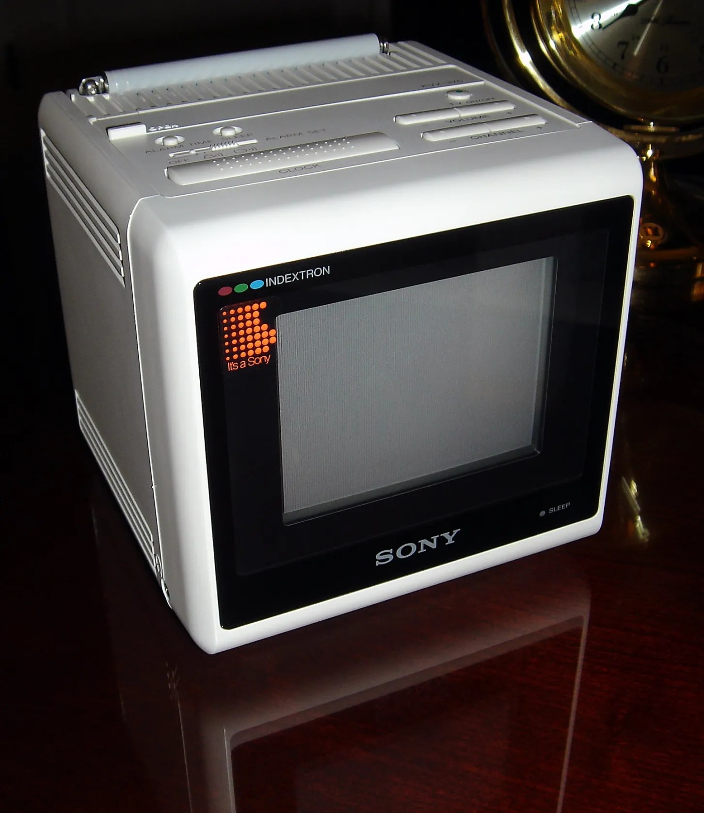
Sony Indextron KVX 370 Watch Cube
Briefly, conventional CRT televisions use 3 guns, 3 electron beams to create color images and use a shadow mask with perforations that block a good percentage of light from getting to the screen. The beam index CRT uses only one gun and one beam and eliminates the shadow mask and complicated convergence circuitry. The tube has a short neck and has the simplicity of a black and white tube. The inner surface of the indextron tube is coated with phosphorescent material in thin, vertical stripes that glow red, green and blue. These stripes are separated by index stripes. The single electron gun emits a beam of electrons which repeatedly scans the face of the tube, illuminating one phosphor stripe at a time. Since the video signal modulates the intensity of the electron beam, it can produce subtle blending of color. An electronic feedback system accurately positions the single beam as it scans the screen. The beam passes through an electronic index window on its way to the phosphor surface. Photo detectors in this window provide input to the circuits that control the electron gun, moving it to the next index location. Opaque guard bands prevent the beam from spilling over onto the adjacent stripes. Since the beam is aimed with precision, the beam diameter can be reduced, increasing resolution. Because there is no shadow mask, almost all the light reaches the screen, consequently the tube can be run at significantly lower power levels. The single beam is controlled precisely and no convergence is required, simplifying the circuitry. The complicated index processing has been packed into three newly developed IC’s developed by Sony, to greatly reduce the size of the television.
A brief abstract from a Sony technical journal published August,1989:
The development of the first beam-index color television for the consumer market is described. The TV uses a 3.7-in beam-index cathode ray tube. A good index signal-to-noise ( S / N ) ratio was achieved by developing a photodetection system and using the 3/4 nonintegral method. Compact size (133 mm×133 mm×133 mm) for portable use was realized by extensively incorporating surface-mounted components, developing an extremely small flyback transformer (FBT), and designing ICs for handling complicated index processing circuits. Solutions to the inherent problems of small television, i.e. heat dissipation and reception by rod antennas, were developed. The heat problem was ameliorated by circuit integration of the index signal process and the design of a low-power-consumption deflection system. Tuner pack technology was applied to pack the index signal processing in a metal shield, thus suppressing extraneous radiation and making non-antenna reception possible.
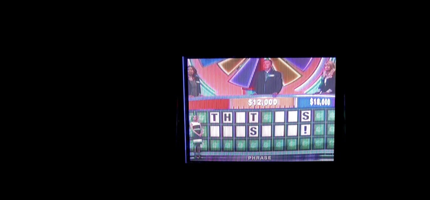
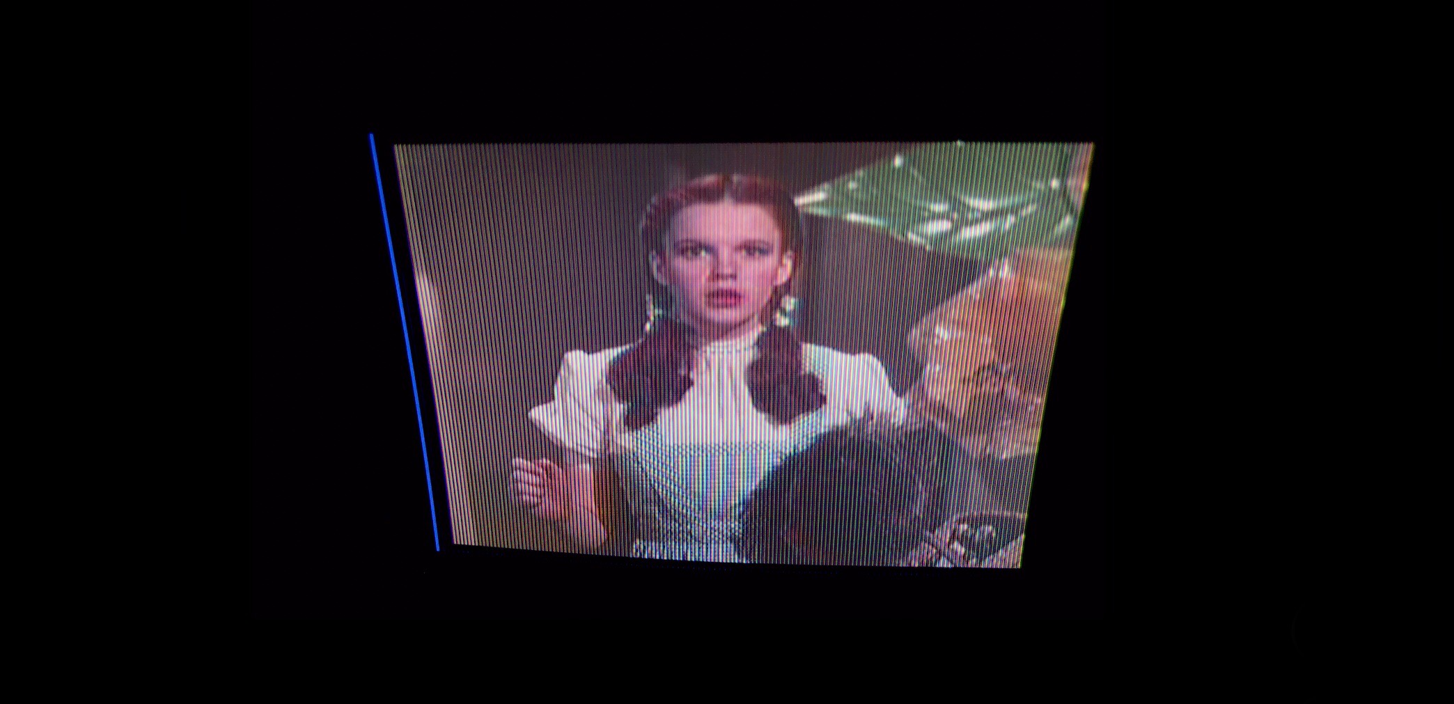
After just a few hours of viewing, I have noticed exceptional color fidelity for such a small 3.7 inch screen. It has depth and dimension with excellent color shading. On the minus side it lacks deep blacks, see Andy’s description below as to the reason for this. In addition the pixel pitch, being the vertical stripes, are quite noticeable while viewing. I believe this is from the alternate index stripes and guard bands which are not illuminated by the electron beam. It is unlike any other color television I have seen.
Update, December 21, 2010, after watching this set the past 6 days, have come to conclusion the contrast is fine, just the issues mentioned above. For older folks out there, the color viewing experience is akin to the old Technicolor movies and television shows from the late 60’s and early 70’s, outstanding depth, color shading and naturalness. Television images vary in quality from program to program, this set seems to bring the best out of high quality telecasts.
I can’t help thinking what may have come had Sony continued development on the Indextron. This was Sony’s first Indextron television other than the previous monitor. I could invision a fine pitch phosphor screen (only 148 triplets were used in the KVX 370) with thinner index stripes and guard bands for increased resolution. I believe they would have improved the contrast ratio. UPDATE, NOVEMBER 19, 2015, SEE THE ABOVE REVIEW OF THE SONY IDX 7000. (The Hitachi beam index CRT shown above proves that super fine pitch phosphors with index stripes and guard bands could be manufactured. The Hitachi tube has 129 triplets laid across a 1.25 inch screen.) Larger full size screens up to 43 inches would have been possible. Think this improbable? When the Trinitron was introduced in 1968, critics said the Trinitron would be confined to small screens, leaving the 3 gun, shadow mask tubes for larger screen sizes. Sony proved the skeptics wrong and created the largest color CRT made, a 43 inch Trinitron. The cabinets for such sets would have been shallower because of the tube simplicity. (It was known they were working on such televisions in the lab.) It was the late 80’s, early 90’s, large screen plasma and LCD flat screens were looming on the horizon. The future was with flat screen technology not the Indextron. Still, had Sony continued to develop the Indextron, we would have seen the finest * cathode ray tube color television ever made, surpassing the Trinitron.
* One limiting factor, no true black since the index stripe is required to “see” the single electron beam so that it can reflect its ultra-violet light generated to the photo diode. Perhaps very low thresholds of light detection could have been developed to overcome this problem but I doubt it would ever be perfect. Please see Page 3A for full description of the Sony KVX 370 Watch Cube.


Tap or click on this image which is shown larger than actual size to see the faint index stripes and run-in area to the left and at the bottom of screen.

There are three index stripes for each four triplets. A triplet is one set of red, green and blue phosphor stripes, and there are a total of 148 triplets. The run-in index stripes are placed well off the viewing screen to the left. A few are visible in this screen shot. Only index stripes are placed in the run-in area, and above and below the main viewing area. The run-in area clocks and starts the index switching. The index stripes below, correct index errors such as magnetic fields. The index stripe is a low persistence P47 phosphor which emits ultra-violet light. The photo detector assembly comprises the condenser plate, the PIN photodiode and the preamplifier and is located outside of the CRT funnel and where attached, the glass is semi-transparent. Aluminum is placed to the surface of the glass in the rest of the inside of the funnel and this diffused reflection is used to increase the condenser efficiency. The PIN photodiode converts the index light from the condenser plate into electric signals. In the beam index system, it is important to have precise beam control (no shadow mask or color selection mechanism). The spot size must be maintained so that it does not spill unto an adjoining RGB phosphor, even though there is a separating aluminum metallic film (guard band). Sony developed interesting circuits to maintain precise control, and they are: 1) dynamic focus; 2) black level current stabilization; 3) peak beam limiter; 4) beam scanning speed control; and 5) horizontal size stabilization. The Black level current stabilization circuit keeps the brightness level constant even though the beam current decreases over time from usage of the television. Notice the perfect purity.

Close up of Sony Indextron KVX 370 viewing screen. The index stripes are visible in this photograph.

This photo shows the run-in index stripe area on the left courtesy J. Halphen.

The Indextron exposed. This view shows the short, narrow necked CRT similar in size to a black and white CRT. Total depth is 135 mm. The right side of the 3.7 inch CRT bell is not metalled and the glass is opaque, semi-transparent. The PIN photodiode can be seen with it’s preamplifier on top of the orange condenser plate. The condenser plate is made of acrylic resin with two types of fluorescent materials injected for converting the 400 nm wavelength of the ultraviolet index light from the P47 phosphor index stripes into 600 nm, near to the spectral sensitivity characteristic of the PIN photodiode. The PIN photodiode converts the index light from the condenser plate into electric signals. The condenser plate is mounted directly onto the surface of the opaque glass area and conforms to the shape of the bell. (See above diagram) The inside of the bell, or funnel is coated with aluminum and this diffused reflection is used to increase the condenser efficiency. The PIN photodiode detects the light from the opaque glass and amplifies the light and sends the index signal through the processing circuit, then passes the band pass filter and divided into three different paths. The first path goes through a limiter and is input to the phase locked loop (PLL). The second path is sent to the start detector, which determines the color switching start time. The third path is the run-in servo circuit. This servo circuit assures that the run-in section index signal, with no relation with the video signals, at the left edge of the screen outside the effective screen can be detected at a fixed level. The single electron beam is precisely modulated and indexed across the RGB phosphor stripes on the screen. There are five additional circuits described above to control the electron beam. The photo below is courtesy of an unknown Japanese collector. His website www.gem.hi-lo.ne.jp/no-koshobu/

A close up showing in detail the condenser plate location and mounting to the CRT bell. You can see the orange plate in direct contact with the bell glass. Photo courtesy J. Halphen.
 Photo courtesy J. Halphen
Posted April 6, 2023
1988
Sony 05DS Indextron CRT

Condenser plate with photo diode
The star of the show, Sony 05DS Indextron color cathode ray tube, an engineering marvel. 3.7 inch measured diagonally with 90 degree deflection. One gun, one electron beam indexed over 148 triplets of RGB phosphor stripes without a color selection shadow mask or aperture grill. In some of the photos below, you can see the transparent glass on the side of the funnel bell and actually see the backside of the phosphor screen. The condenser plate is affixed to this area which “reads” and amplifies the light energy from the single electron beam by a photo diode attached to the condenser plate, which in turn relays this information to the color processing chip. Description simplified, see the wider description above. We purchased this CRT from a gentleman in Japan whose father worked at Sony. I’m attempting to contact the gentleman to learn more about his father’s work. If successful, I’ll publish what we learn.


More KVX 370 photos.


The former owner said this set was used only a few times. When I acquired this television, it appeared in mint, unused condition, in original box, packing materials and all paper work. Upon power up, the bottom 1/4 of the image was cut off. The set has a reputation for leaking capacitors, so I asked Andy Cuffe who has repaired 5 or 6 of these sets prior, to repair my set. Here is Andy’s commentary: “I’ve pulled the chassis, and apart from the leaking caps, it looks like new. Since it hasn’t been used much, there isn’t much corrosion of the circuit board traces. In this picture, the arrow is pointing at a pool of electrolyte at the base of one of the bad caps. Ironically, the brown caps are supposed to be high quality, high temperature caps, but they have faulty seals. The regular caps still look like new.”

A total of 19 caps were replaced. Andy sent these bad caps pictured below.

Andy continues, “I have replaced all the caps, repaired a few minor corroded spots, and soaked the boards in alcohol to remove all traces of electrolyte. I need to reassemble it, test it, and take care of any other problems. Good news, the Indextron is back together and working. I will touch up a couple of adjustments, and test it for a few days. The contrast is as good as I’ve seen on one of these, but the purity could be a little better at the edges. I can usually improve the purity with a few minor adjustments, but it will never be perfect. The contrast will never be very good because it can’t turn the beam completely off or it would lose the index signal. The focus adjustment greatly affects the black level since a bigger spot produces a less clear index signal (it automatically increases the brightness to maintain the correct index amplitude). As the CRT ages and loses sharpness, the black level gets worse. You don’t have to worry though, I repaired a very heavily used one and it still produced an acceptable picture, but with noticeably worse blacks. I was able to get the best purity I’ve seen on the 6 or so of these I’ve worked on.”
The repaired television arrived safe and well packed. I adjusted the brightness and picture controls to my taste and below, a few screen shots. I find this television to have exceptional color fidelity, but lacks the ultimate black levels of conventional color CRT’s. The phosphor stripes are quite visible as well. Over scan is average, not the worst, not the best and just a minor purity issue at the extreme left side. I can see it only when background image is all red, about 2 mm of orange tinge. Viewed from a distance of 3 to 4 feet the phosphor strips are not discernible and the viewable area of the screen is perfectly flat which helps to reduce reflections.
As with all screen shots on this website, untouched, only re-sized. The signal source is by the antenna input (also has a video input) fed by a ATSC digital signal converted to NTSC analogue by a digital converter box. The CRT is an Index Beam, one gun, one beam design which eliminates the shadow mask. Virtues are exceptional brightness, natural color and perfect convergence.
I highly recommend Andy Cuffe for restoration work you may need on vintage televisions. He can be contacted at http://www.Videokarma.org website and forum.
I have tried to capture the best quality screen shots below, but this can prove to be difficult. The shots were captured on the fly without aid of freeze frame capability or a tripod. The scenes are ever changing and with that goes focus, contrast and color values. It is best to take the shot with no or very low ambient light and to fill the entire viewfinder or screen with the television image. This allows the image sensor on the camera to capture only the subject light from the display and not having the camera try to adjust to the surrounding light which usually results in an over exposed screen shot. These shots are larger then actual size to show more detail.
October 8, 2013: It is recommended that these images be viewed with high density display devices such as an iPad with Retina display for maximum image detail.


Click on below screenshot for enlarged image, click again for full size to examine pixel structure. First click is double actual size and second click is 3.25 times actual size on a 1600 resolution monitor.


UPDATE, MARCH 1, 2020
Nine years, three months after my white KVX 370 was restored by Andy, it’s still going strong. Brief recap, (no pun intended) this particular set is well know for bad leaking “high quality” capacitors. Once the bad caps are excised, the set is very reliable. Almost 10 years after replacement with no problem is proof. The set was new in box when purchased. Today while operating, it has that “new electronics smell” which by the way, is not objectionable. We made this video to replace the two videos we made 2 years back. Those videos reflected my inexperience with my new Sony A6300 and displayed ugly frame bars traversing the screen. Thanks to Wayne B. who instructed me to set the shutter speed below the frame rate, 1/30 second on another screenshot project with my Westinghouse H840CK15, we now have a frame free video. FL: 42mm, SS: 1/20, Aperture: 20, ISO: 6400, WB: Daylight. Camera: A6300.
A collection of screenshots taken during the video. I used the same camera settings for video and still shots.


Note: Watch my other videos here , which are all in HD. Select the HD icon in settings. (The gear) The above two inbedded videos are not in HD, but simply select this link and you can access them in HD.
You may be wondering why so many screen shots? Well this Sony is extremely rare and to find one in working condition is equally rare. Finding a service technician is rarer still, so I’m pleased to display images from a working Indextron. 🙂 When the Black version is up and running, I will post screen shots from this model as well. See information on the BLACK VERSION OF THE KVX 370 on page Three-A.


Posted March 26, 2023


1989
Sony KV-4SV2 Side Story
The Japanese market model from 1989 in blue. This model is identical in all respects to the above American models KVX 370, but with the addition of remote control which I do not have. You can see the sensor in the lower left of the cabinet. The remote is credit card in size with basic functions. This set is in good condition and working.


1992

Sony XAV-U50 Mobile
Here we have a mobile Indextron from 1992. We have sparse information on this model, but know we have the head unit only, no cables, power supply, remote or accessories. The CRT is 4.25 inches, uses two photo detectors and powered by DC 12 volts. The cabinet is 7W X 4H X 6.75D in inches.


December 31, 2023


1992
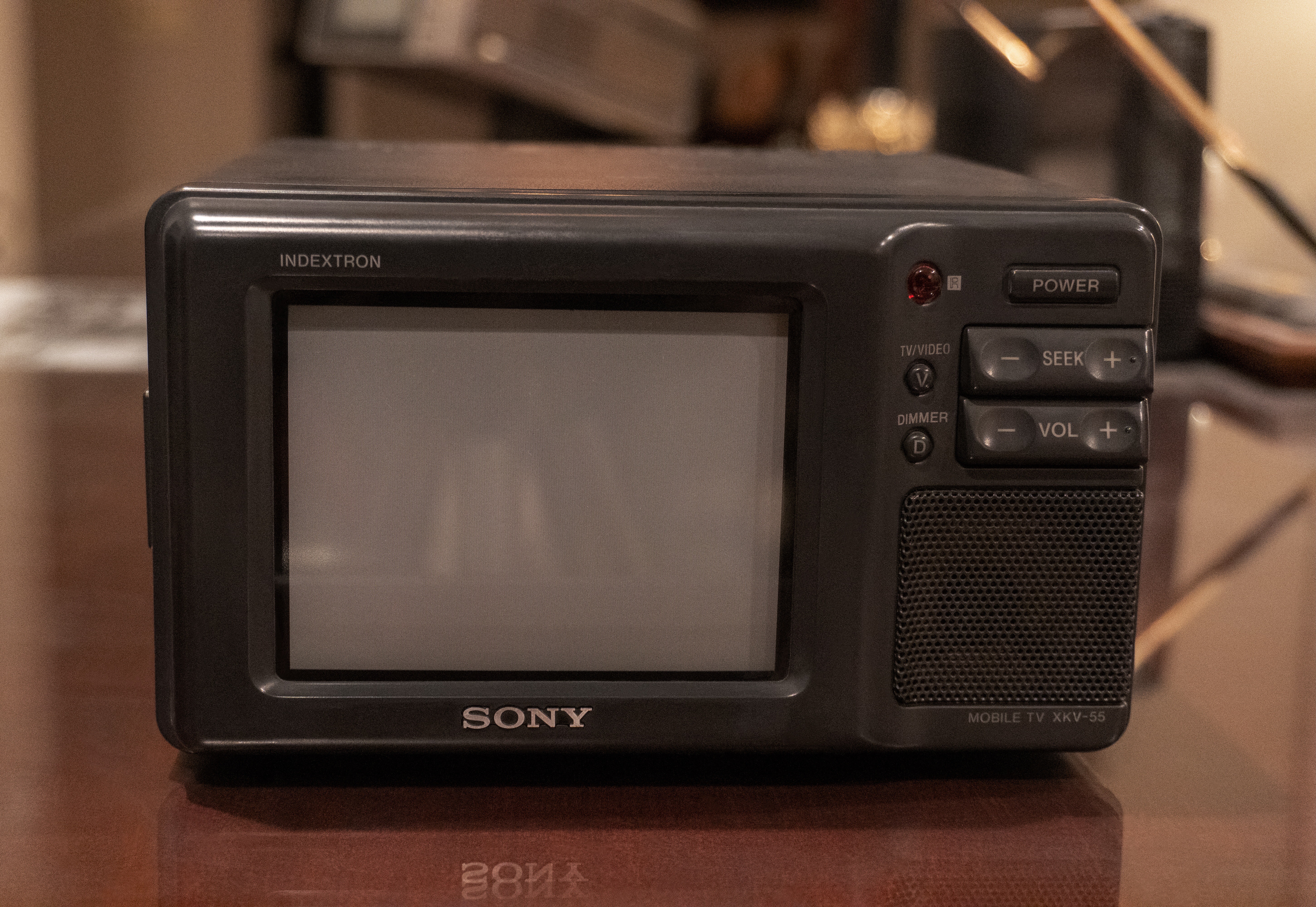
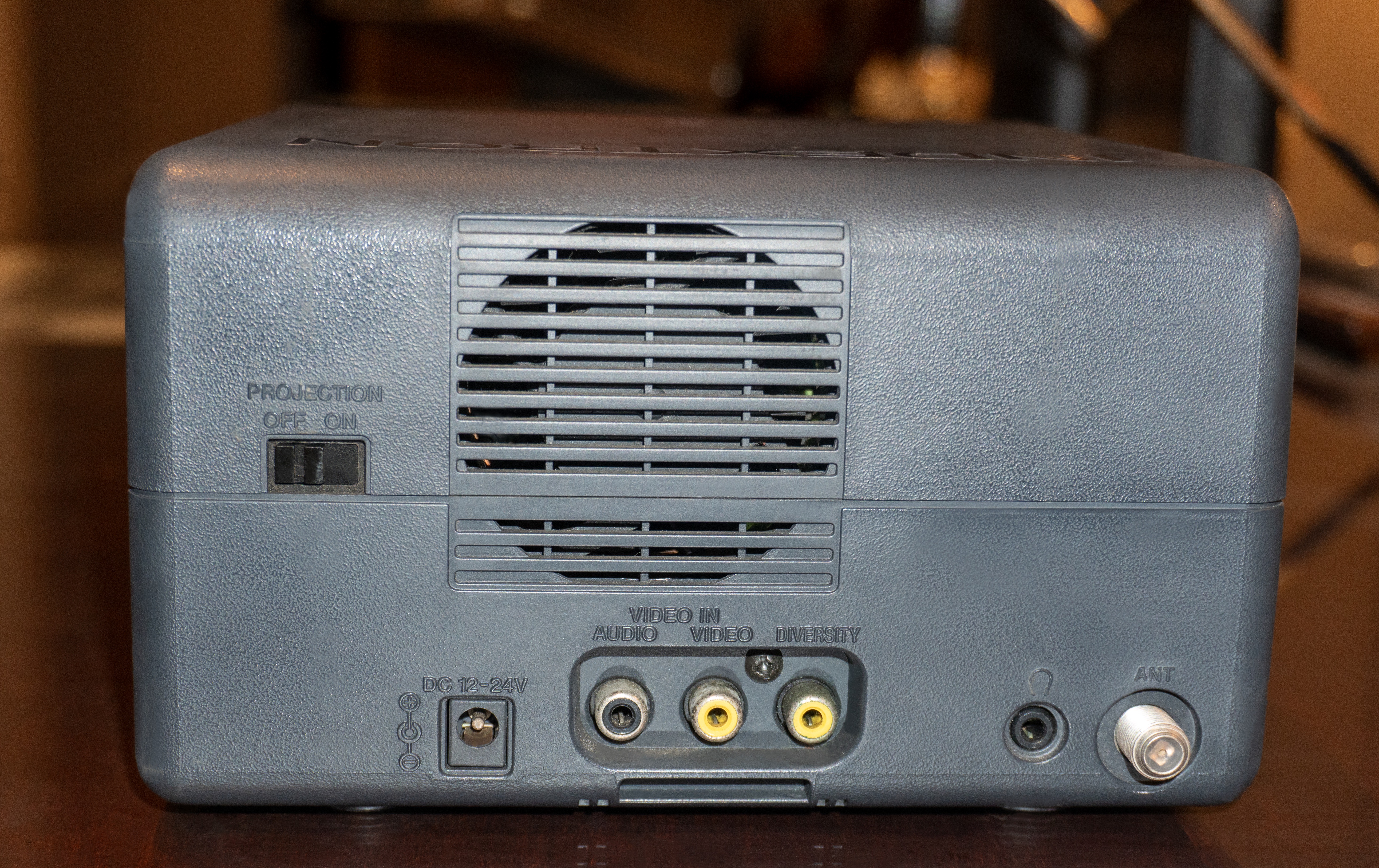
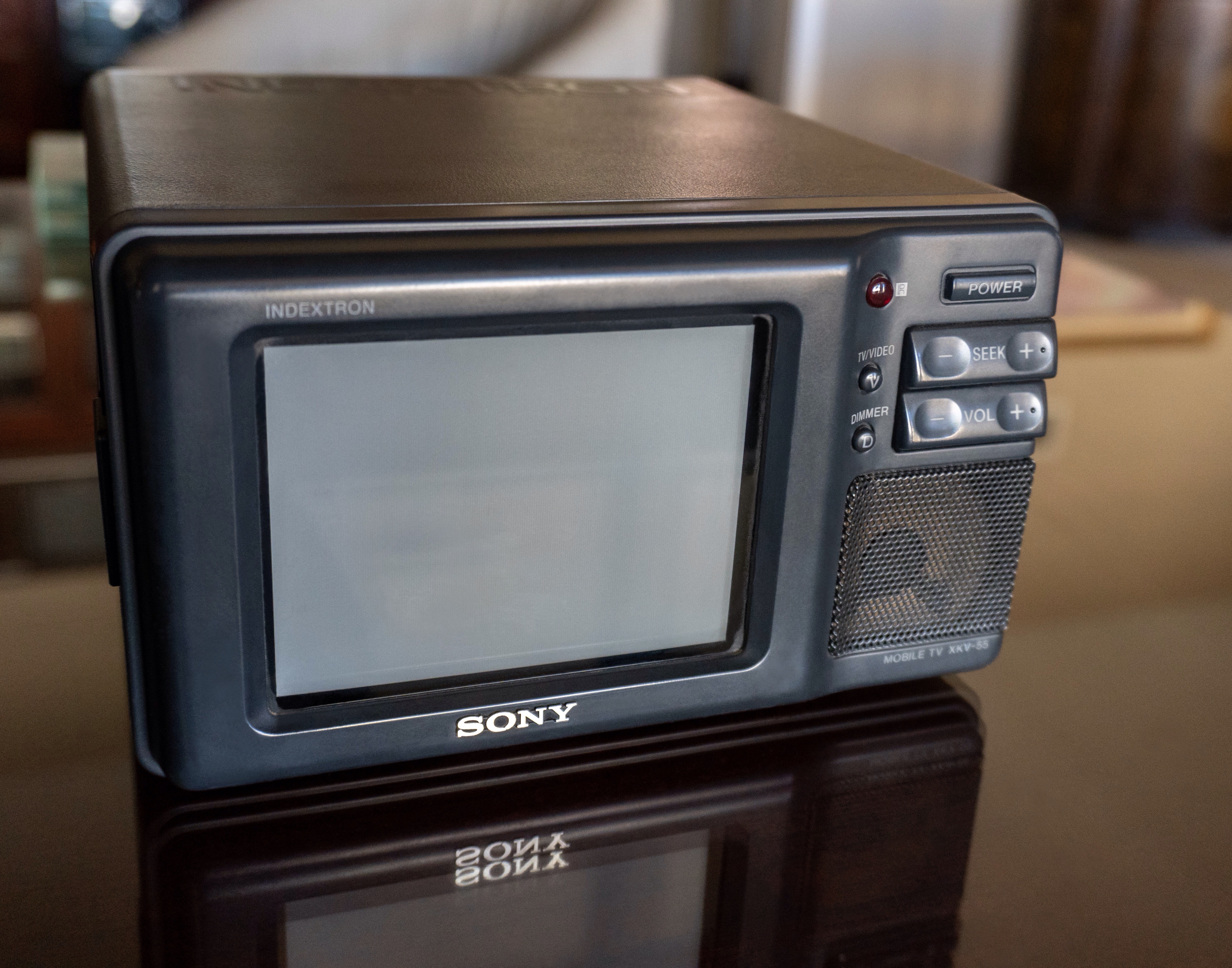
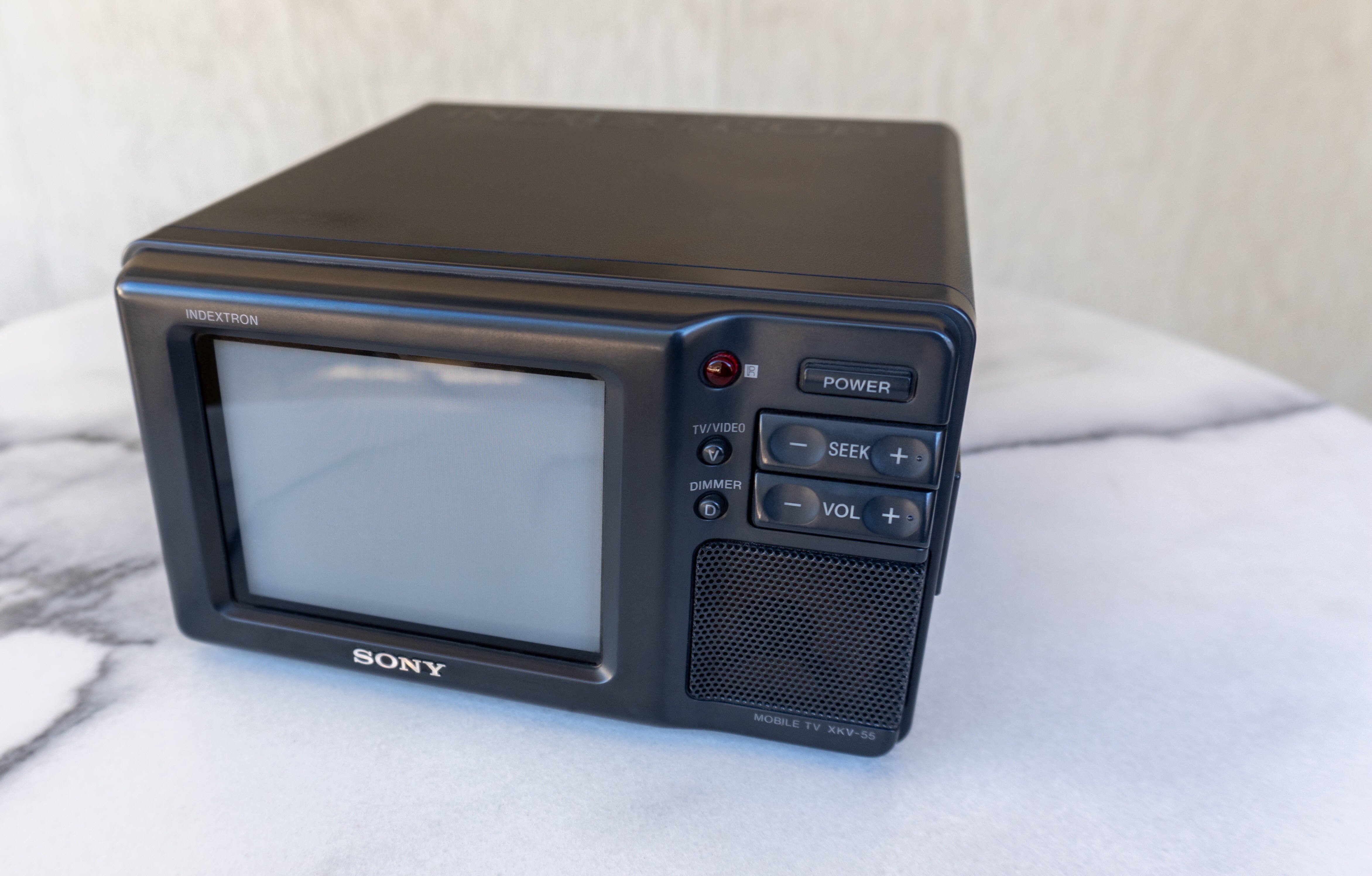
Sony XKV-55 Mobile Indextron
Same description as the above XAU-U50 with a cooling fan, antenna, earphone, A/V and diversity inputs, 12-24V power operation. I suspect this unit requires a high current power supply up to 24 volts which I do not have at the moment. Does not need ancillary equipment to run the set. 4.25 inch Indextron CRT. A curiosity is the projection switch on the rear of the cabinet. What is this? Researched and found the switch is to flip the image upside down for roof mounting in a vehicle. Measures 7.0 W X 4.0 H X 7.75 D in inches.

Next, Page 4K.

Hello, I have a KVX370. I turn it on every so often to see if it is still working. The last time I turned it on I had the same problem with the screen getting smaller. I am assuming it is the leaking capacitors problem. Is this an expensive fix or a worthwhile repair?Is it possible to direct me to your repair technician Andy Cuffe
It very well could be the problem. Once the bad batch of leaking caps are replaced, the set is stable. Considering the rarity of your set, we think it’s a good investment to repair. We will forward your question to Andy. Hope it’s an easy fix.
Visions4 Magazine
[…] Apparently there’s a Hitachi beam index TV that was officially larger than the CT-101, but in reality was slightly smaller. […]
[…] Apparently there is a Hitachi beam index TV that was formally bigger than the CT-101, however in actuality was slightly smaller. […]